Loads versus capacity
There are two methods to calculate the ratio of loads against section capacity. The first is to calculate the Utilisation of the section using the vector method. The second method calculates the moment load to capacity ratio at constant axial force M/Mu.
Utilisation
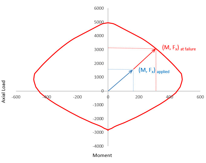
Utilisation (also known as the vector method) is expressed as:
As shown in the diagram above, (Fx, Myy, Mzz)applied are the applied axial load and bending moment about yy axis and zz axis respectively, constituting the resultant applied load vector.
(Fx, Myy, Mzz)at failure are the axial load and bending moment about yy axis and zz axis respectively at failure. These constitute the resultant load vector at failure along the applied load vector (Fx, Myy, Mzz)applied.
M/Mu
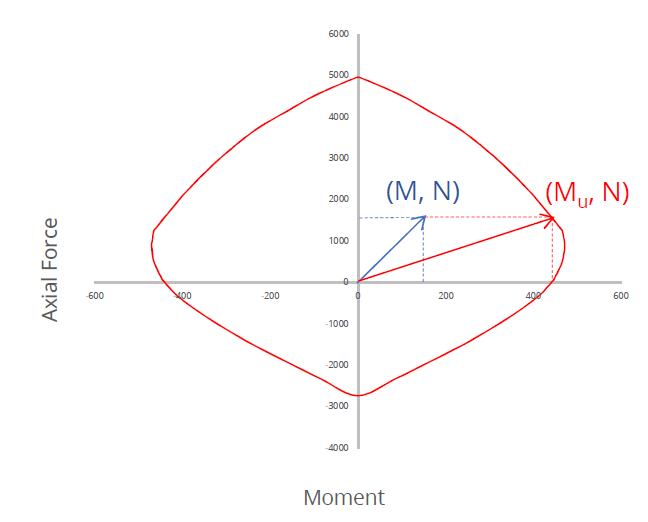
Moment utilisation at constant axial force is expressed as M/Mu
As shown in the diagram above, M is the resultant bending moment applied to the section.
Mu is the section's bending moment capacity for the applied axial load (N) in the direction of applied resultant moment (M), i.e. along the same moment angle.
Example
The following example shows calculation of loads against section capacity ratio using the two methods:
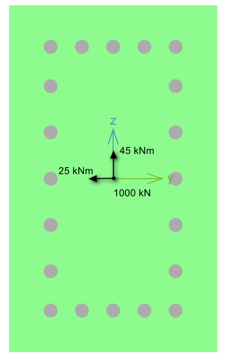
Scenario:
| Section | Fx (kN) | M yy (kNm) | Mzz (kNm) | Utilisation | M/Mu |
|---|---|---|---|---|---|
| 500 x 300 mm RC | 1000 compressive | 25 tension at bottom | 45 tension on left | 0.31 | 0.213 |
Calculating Utilisation
Inputs:
Results:
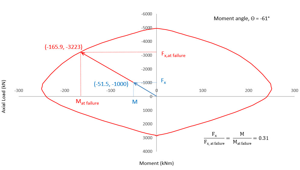
Therefore, the applied load vector (-1000 kN, -25 kNm, 45 kNm) can be upscaled by a factor of approximately , until it reaches its capacity (-3246.4 kN, -81.2 kNm, 146.1 kNm).
Calculating M/Mu
Inputs:
Results:
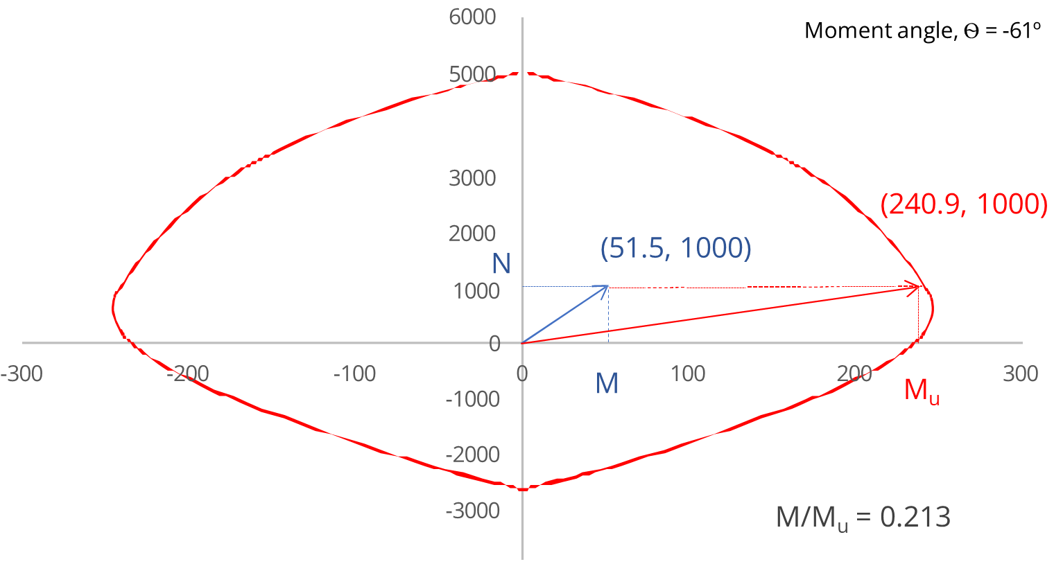
Therefore, the section has a bending moment capacity, Mu=240.9 kNm at a moment angle, when subjected to a compressive axial load, N = 1000 kN.
M/Mu versus Utilisation
There may be significant differences in the loads versus section capacity results reported using these two methods, particularly for sections with asymmetric interaction diagrams. In such cases, utilisation provides a much better indication of how hard the section is working as compared with M/Mu.
In the following scenario, for example, the N-M interaction below for an RC section with bottom reinforcement only, demonstrates that for an applied load of N = 5600 kN (compression) and Myy = 116.5 kNm (tension at top).
The M/Mu reported is 0.25 even though the point lies outside of the N-M interaction plot.
The Utilisation reports utilisation as 1.1 for the same applied load.
In thise scenario, utilisation results provide a better understanding of the overall section capacity.
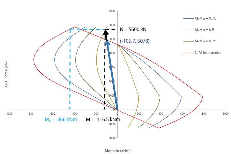
N-M Interaction diagram for an asymmetric section along with N-M curves for M/Mu = 0.25, 0.5 and 0.75.