Element Axes
For each element there is an element axis that is used both to establish the element stiffness relative to the structure as a whole and to establish the direction of element loading as well as element analysis results
The element axes are defined relative to the undeformed geometry of the structure. For linear analysis these remain unchanged during the analysis, but for nonlinear analysis, element axes will be updated during the analysis according to the current deformed positions of the elements..
Beam Type Elements
Beam elements including bars, rods, ties and struts are defined by two nodes locating the ends of the element. The x axis of the element is along the axis of the element (taking account of any offsets) from the first topology item to the second.
The definition of the element y and z axes then depends on the element's orientation, verticality, orientation node and orientation angle. The element is considered vertical in GSA if the element is within the “vertical element tolerance”.
Non-vertical elements
If an orientation node is not specified, the element z axis of a non-vertical element defaults to lying in the vertical plane through the element and is directed in the positive sense of the global Z direction. The element y axis is orthogonal to the element z and x axes. The element y and z axes may be rotated out of this default position by the orientation angle (β).
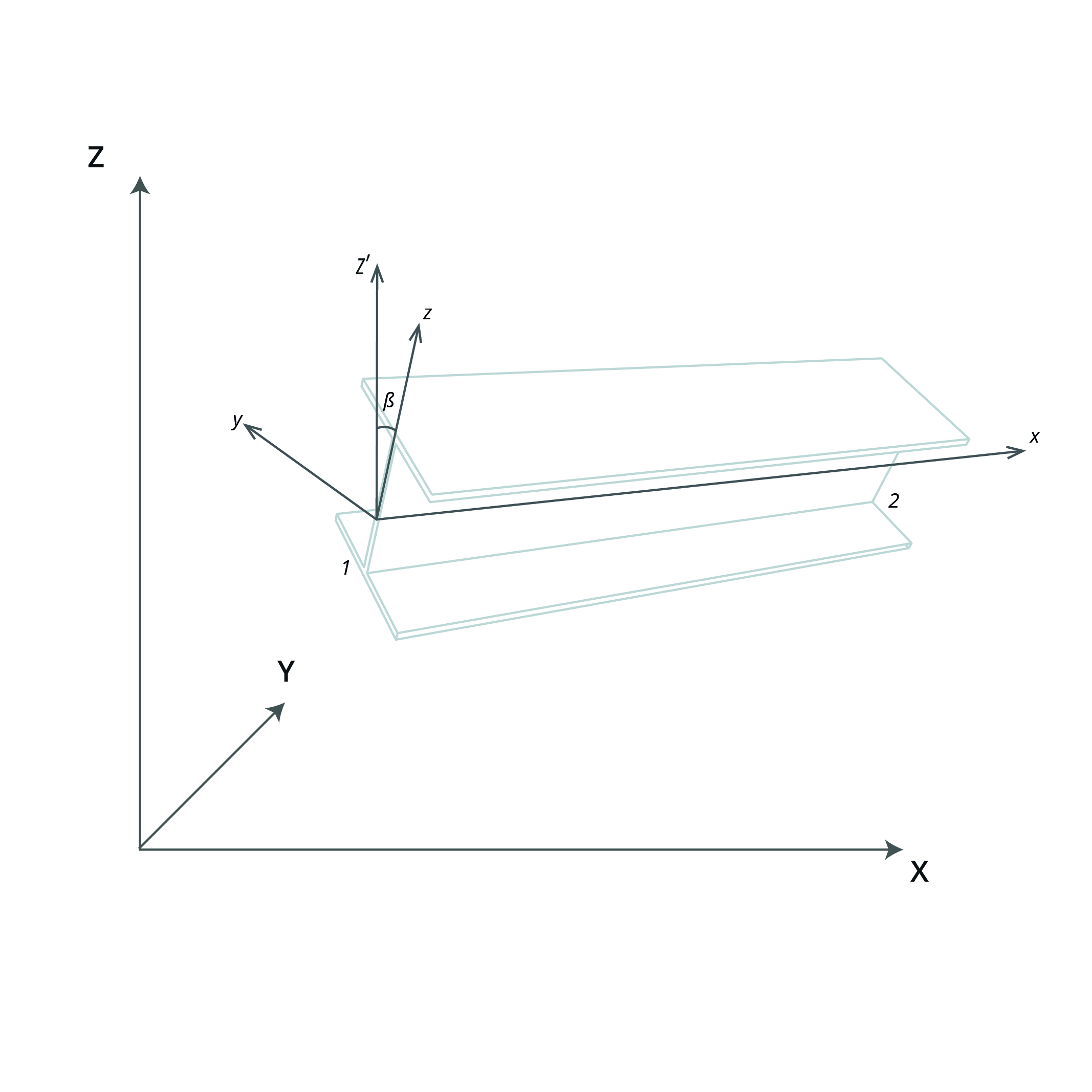 (Beam element axes)
Vertical elements
If an orientation node is not specified, the element y axis of a vertical element defaults to being parallel to and is directed in the positive sense of the global Y axis. The element z axis is orthogonal to the element x and y axes. The element y and z axes may be rotated out of this default position by the orientation angle.

Orientation Node and Angle
If an orientation node is specified, the element xy plane is defined by the element x axis and a vector from the first topology position to the orientation node, such that the node has a positive y coordinate. The element z axis is orthogonal to the element x and y axes. Specifying an orientation node overrides the “vertical element” and “non-vertical element” definitions described above. The element y and z axes may be rotated out of this default position by the orientation angle.
With an orientation angle the element y and z axes are rotated from their default positions about the element x axis by the orientation angle in the direction following the right hand screw rule. This occurs regardless of whether or not the element is vertical and of whether or not an orientation node is specified.
Spring and Damper Elements
For a spring (including Gap, Friction & lockup elements) or damper element wreplica*ith finite length, the element axis are defined in the same way as the beam element axes. For a spring and damper element with zero length, the element axis is the nodal constraint axis of the first topology node of this element.
Cable Elements
Cable elements act only in the axial direction, so only the x axis is defined following the same definition as the x axis of a beam element.
Link Elements
The local axes of link elements are the same as the constraint axis of the primary node.
Quad and Triangle Elements
2D element local axis is the axis referenced by the element stiffness and forces, moments and stresses, the xy plane of the 2D element local axis is always co-planar with the element plane. 2D element local axis can be defined by global axis or a user defined axis or by the nodes defining the 2D element (topological), the axis used by 2D element to determine its local axis is defined in 2D element property. User defined axes can be Cartesian, cylindrical or spherical.
Typically using a global axis or a user defined axis to define 2D element local axis can result in consistent local axis direction for all the elements in the mesh.
2D element local axis defined by element topology
If "topological" is used in 2D element property, 2D element local axis is defined as follows: The z axis direction of the 2D element local axis is always perpendicular to the 2D element plane and it is defined as
Then the three axes of the 2D element local axis are defined as:
where , , , & are the coordinates of topology nodes 1, 2, 3 & 4 of the element, the coordinates of the node should include any offset.
2D element local axis defined by global or user defined axis
If global or user defined axis is used in 2D element property, the x axis of 2D element local axis is the projection of the control vector onto the 2D element plane and the other two axes of the 2D element local axis can be determined accordingly as shown below.
The control vector depends on the type.of the user defined axis,
If it is Cartesian, the control vector is the same as the axis of the Cartesian axis,
If it is Cylindrical, the control vector is the projection of vector onto the plane of the cylindrical axis, the vector is the vector from the origin of the cylindrical axis to the element center.
If it is Spherical, the control vector is equal to the vector from the origin of the spherical axis to the element center.
If the control vector is perpendicular to the 2D element plane, then the normal to the plane defined by the control vector and the z axis of the 2D element property axis will be used as the control vector . For Cartesian axis, the new will be the same as y axis of the 2D element property axis.
Once the control vector is known, the 2D element local axis can be calculated as follows:
, & are the three axes of the 2D element local axis.
If an orientation angle is defined, the calculated 2D element local axis is rotated by the orientation angle in a positive direction about the element z axis.
Brick, Wedge, Pyramid and Tetra Elements
3D element local axes may be defined either by reference to an axis set or topologically. This is determined by the axis system defined in the 3D element property. If the axis system is 'global' or user defined then the specified axis set is used. If the axis system is 'topological' then the local axes are based on the element topology. User defined axes can be Cartesian, cylindrical or spherical.
Typically defining 3D element local axes by reference to an axis set results in more consistent local axes in the mesh.
3D element local axis defined by element topology
If "topological" is used in 3D element property, 3D element local axis is defined as follows: The z axis direction of the 3D element local axis is always perpendicular to the 2D element plane of the base and it is defined as
Then the three axes of the 3D element local axis are defined as:
where , , , & are the coordinates of topology nodes 1, 2, 3 & 4 of the element.