Concrete 2D member design
Introduction
Concrete 2D member design is a reinforcing option for slabs and walls that allows the design and rationalisation of reinforcement. It is a different approach to the existing RC slab contouring in that it gives a single bar size required over the whole member plus patches where extra reinforcement is required (ie at slab/column connections).
2D member design is a design task, which means that you set up and run the design calculation, then display the results.
Video tutorial
The following video describes how to set up and use the reinforced concrete member design module in GSA. Topics covered in this video include:
- Setting up global design parameters
- Setting up member properties
- Running the concrete member design module
- Displaying reinforcement
Oasys GSA - 10.1 RC Member Design
Setting up the design
- Open specification > Design and set the Concrete design code.
- Open materials > Concrete and add a grade if necessary.
- Open materials > Reinforcement and add a grade if necessary.
Setting up the 2D members
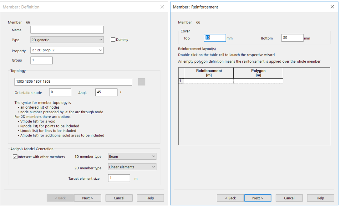
- Member: Definition - Ensure that the 2D member orientation angle is set correctly for the required X direction reinforcement (Properties pane or Member definition wizard).
- Member: Reinforcement - Set the top and bottom cover.
Designing the reinforcement
-
Analyse the model and create an Ultimate limit state combination or Envelope.
-
Add a new Design task (on the GSA toolbar or Design > New design task in the menu).
-
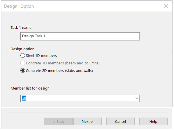
Design: Option
- Name the task if required.
- Set the design option to Concrete 2D members.
- Adjust the member list if required.
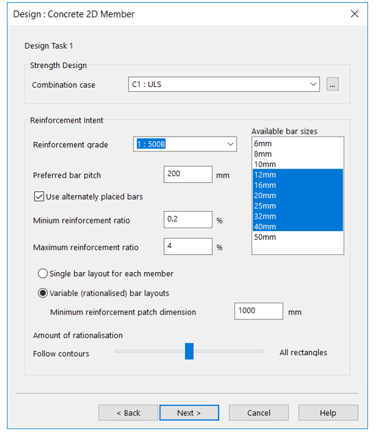
Design: Concrete 2D member
-
Set the Strength design > Combination case.
-
Choose the Reinforcement grade (if this is blank then you need to create a grade).
-
Set the Preferred bar pitch (default 200 mm).
-
Highlight the bars in the Available bar sizes list to use in the design.
-
Check
- Maximum and minimum reinforcement ratios
- Single or rationalised bar layout
- Minimum rebar patch size (for additional rebar over and above the default for the member)
-
Adjust the Amount of rationalisation slider on subsequent uses if the patch shapes were not as desired.
- Design: Task option
- Don’t design now saves and closes the dialog on Finish.
- Design will create the reinforcement and log the results in the Member definitions.
- Check will check that previously defined reinforcement is still acceptable for the new loading.
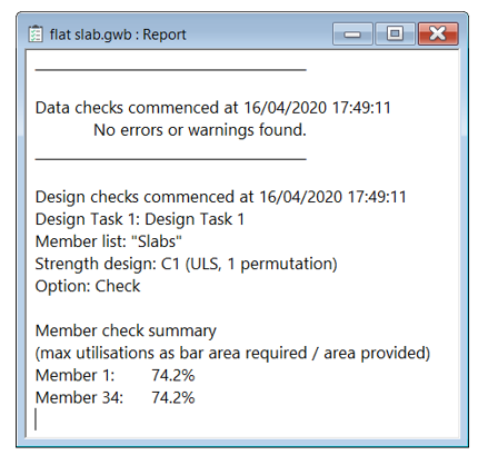
The report window will now show the high-level results.
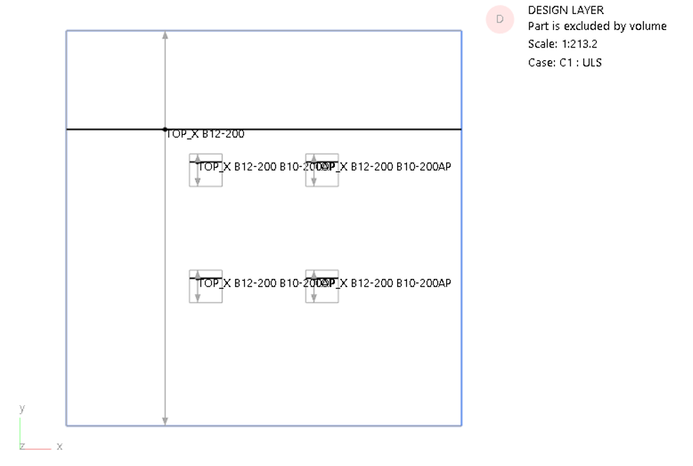
Displaying the reinforcement
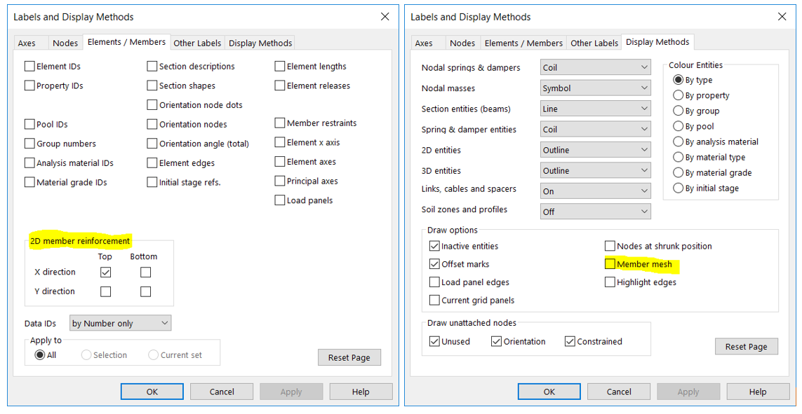
- Ensure that you are on the Design layer
- Call up the Labels and display methods dialog (or Graphic settings > Labels)
- Elements / Members – check the 2D member reinforcement you wish to display
- Display methods – it can help to switch off the Member mesh to make the reinforcement marks clearer)
Editing the reinforcement
To edit and inspect the details of the reinforcement:
- Select the 2D member and run the Wizard.
- The Reinforcement is recorded on the second page of the Wizard.
The text callout is in the first column and the extent in the second: