Creating 1D members
This tutorial focuses on drawing 1D members in the Graphical view. To define the 1D section property see our step-by-step instructions in the 1D member and element properties section
Add 1D member in the Graphical view
Ensure that:
- The grid layout is set to the desired spacing - this determines the grid points you’ll be snapping to.
- The correct grid plane is set - this determines the plane you will be drawing on.
- The grid display is on (Use the Draw grid shortcut or Ctrl+Alt+G to toggle the grid on and off).
- The graphical display is set to the Design layer.
Use the Add entities sculpt tool (Ctrl+Shift+Alt+E)
Set the Member type as either 1D generic, beam or column in the Properties pane.
Set the Property, Group, Orientation node, Releases, Offsets and 1D analysis type as desired.
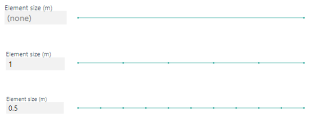
Set the desired target finite element size. The default of none means that GSA will not break the member into smaller elements.

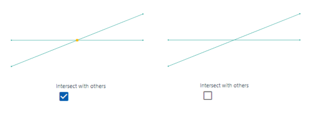
Select how you want the member to interact with other members. By checking the box Intersect with others, the member will be broken into multiple elements if it intersects with another.

Click on the Graphical view to place the member end nodes. To create a member that consists of more than 2 nodes (for example, a kinked beam), hold down the Ctrl key to add a chain of members. Release Ctrl before defining the last node.