Creating and manipulating geometry
As described in Design layer vs. analysis layer explanation, geometry can be represented in either the Design layer as members or in the Analysis layer as finite elements.
It is possible to create and manipulate geometry in either layer. Creating and manipulating all geometry in the Design layer is, however, recommended. Using the Create elements from members tool to generate the analysis layer finite elements is recommended since members represent the physical entities.
The three most common methods of inputting and manipulating data include Sculpting tools, Manually editing tables and Copying.
Sculpting
The easiest way to create geometry is by using the sculpt tools to click and create the geometry in the graphics window. Use the sculpt toolbar to define geometry in the graphics window.
Manually editing tables
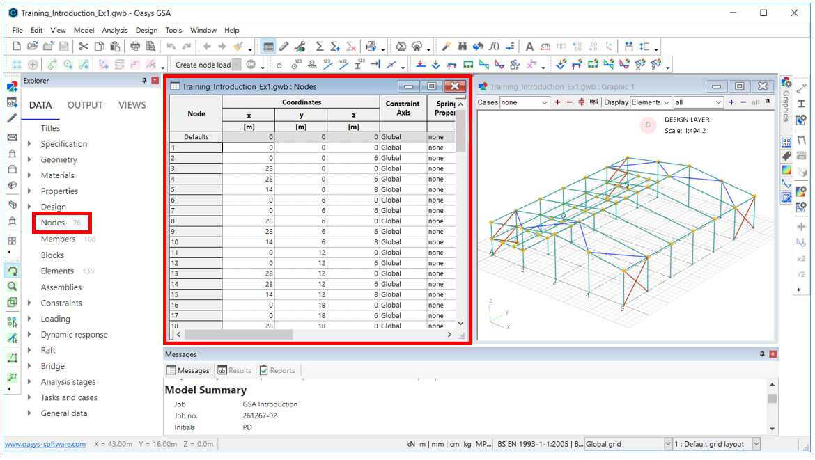
For example, to edit the node positions, go to Explorer pane > Data > Nodes to bring up its corresponding input table.

Copying
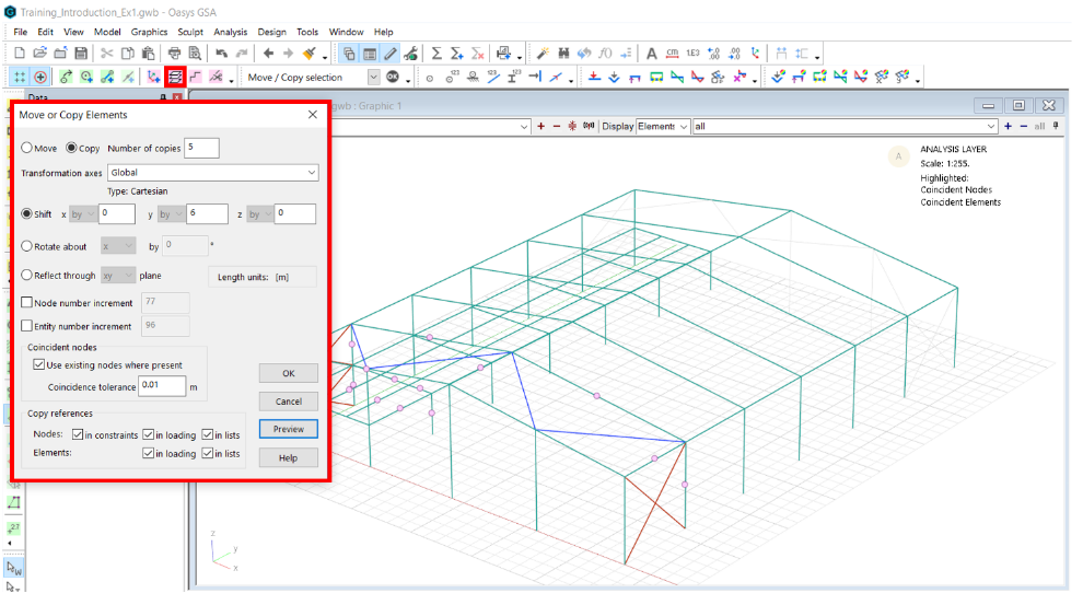
Select an entity and use the Copy icon: or Ctrl+Alt+C to duplicate existing geometry to extend the model.

Additional data inputting
Data can also be inputted:
- Via a text file (advanced option) - Copy data out in GWA format, edit, and replace
- Using an API - Using an Application Programme Interface to create and edit GSA files