Loading
Viewing loads
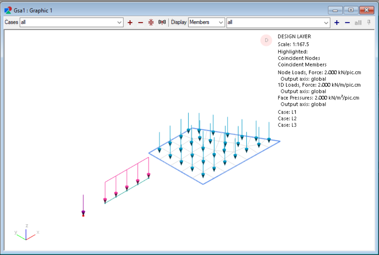
For a quick view of all loads applied to your structure for a particular load case, click on the Show load diagrams toolbar button  then select to the desired load case in the cases dropdown.
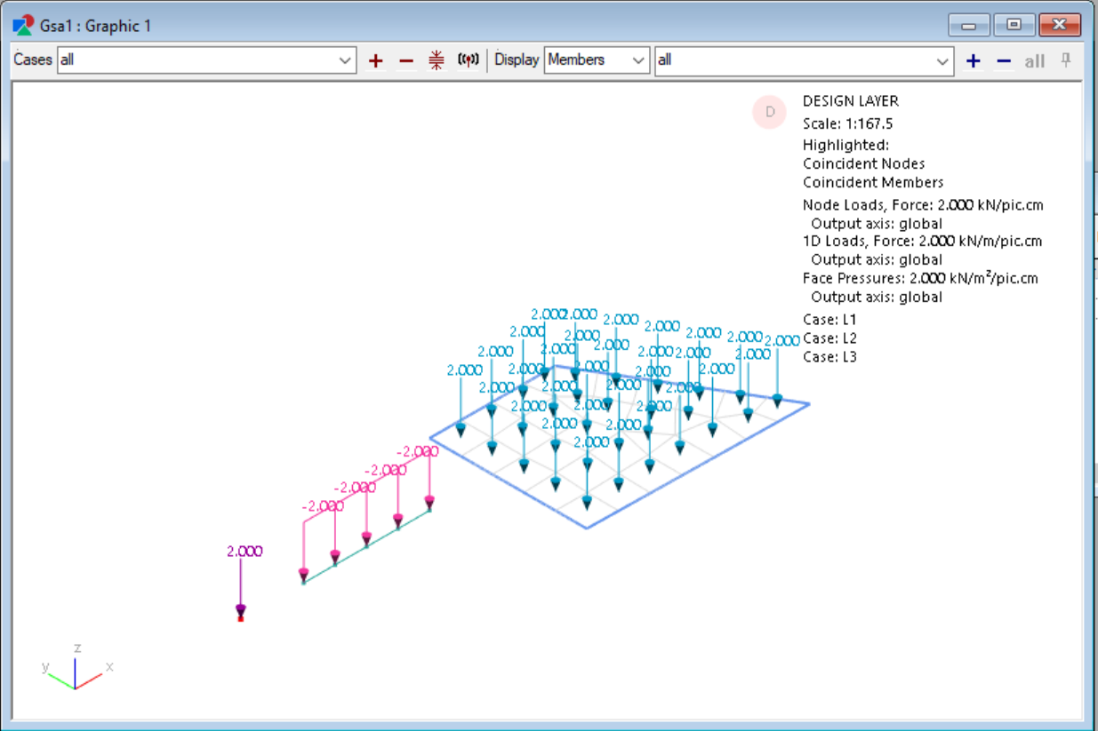
To annotate the loading values in the Graphic view, use the keyboard shortcut A and then graphically select which loads you want to annotate.
Note: All loads shown are drawn based on element locations. If you're in the Design layer and the loads are not being drawn in the right place, it could mean that the members and elements are out of sync.
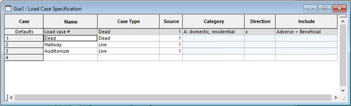
Load case specification
In GSA, loads are applied to load cases. The following describes how to set up your load cases to keep track of your loads.
Note: All these fields are optional. You can still apply loads to GSA without filling in the descriptions; however, case names can be used to more easily refer to the load cases and case type is used for automatic load combinations.
-
Go to Explorer pane > Data > Loading > Load case specification.
-
Specify the Name, case type, source and other categories for each load case by filling out the specifications in table.
Nodal loading
The following steps show how to apply a node load to a particular node. Similar steps can be taken to specify an applied displacement or settlement at a particular node.
Method 1: Apply node load to a selection of nodes using the sculpt tool
- Use the node selection tool (keyboard shortcut n) to select nodes on the graphic view.
- Go to Sculpt > Create Nodal Loading > Create Node load... to open the node load wizard.
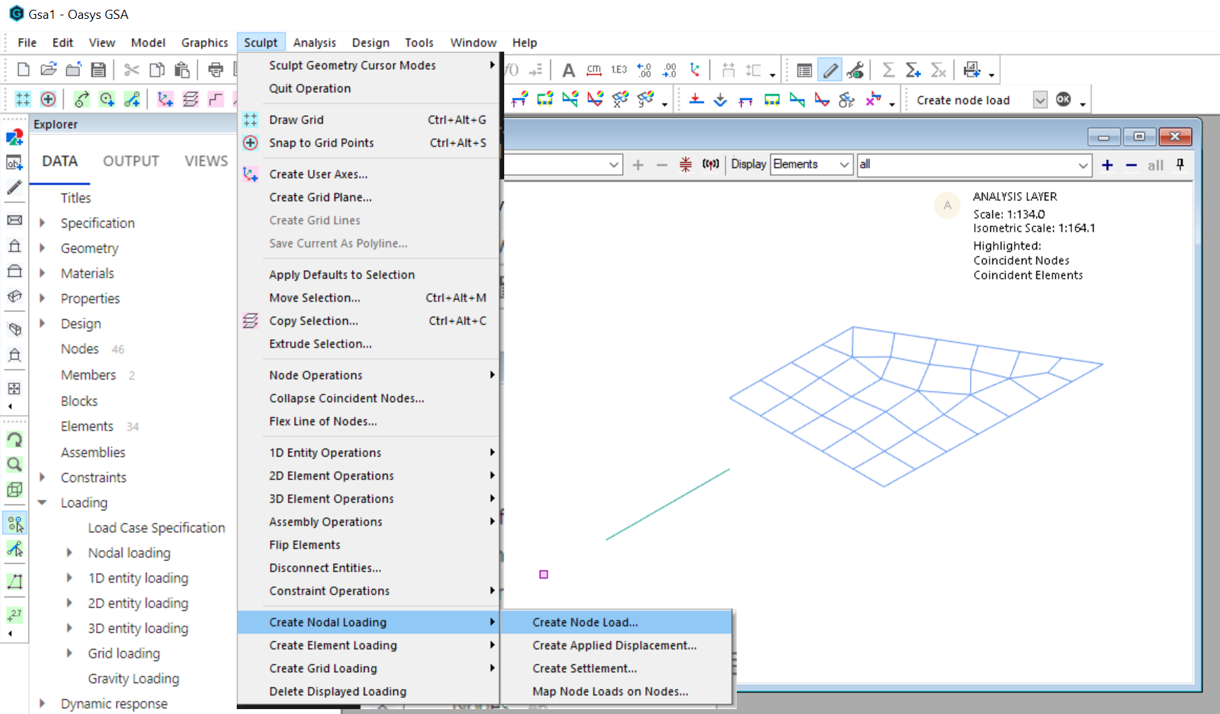
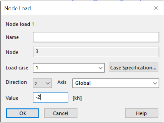
- Enter the load case, direction, axis and value then click OK to apply the load.
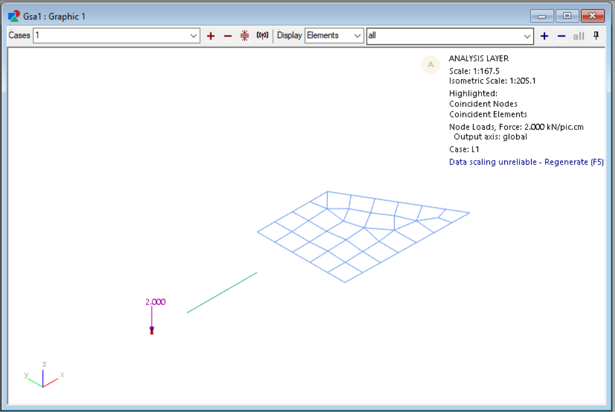
- Click on the Show load diagrams toolbar button to view the load.
Method 2: Apply node load to a selection of nodes using the data table
-
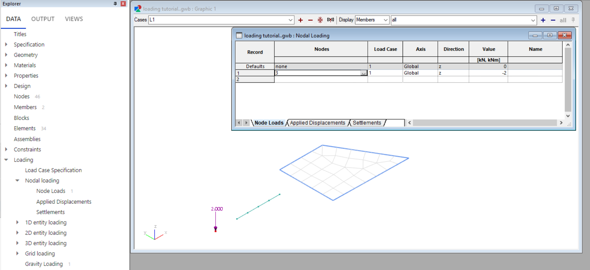
Go to Explorer pane > Data > Loading > Nodal loading > Node loads to open the node loads table
-
Enter the nodes numbers you want to apply the load to in the table.
Tip 1: You can use the keyboard shortcut N to select nodes on the graphic view, and then select Ctrl+C to copy and Ctrl+V paste the selected nodes into the nodal loading table.
Tip 2: You can also specify nodes by groups (e.g. G1 for group 1) or lists (e.g. 'list name').
- Specify your load case, axis, direction and magnitude.
1D entity loading
For 1D entities, you can apply loads to a member or an element. See the member and element loading explanation for more information on what each means.
The following steps show how to apply a beam load to a 1D member. Similar steps can be taken to specify other 1D loads for members or elements.
Method 1: Apply beam load to a selection of members using the sculpt tool
- Use the elements/members selection tool (keyboard shortcut E) to select members in the graphic view.
Note: Make sure you are in the design layer to select members. If you are in the analysis layer, the elements/members selection tool will select elements.
- Go to Sculpt > Create member/element loading > Create beam load... to open the beam load wizard.
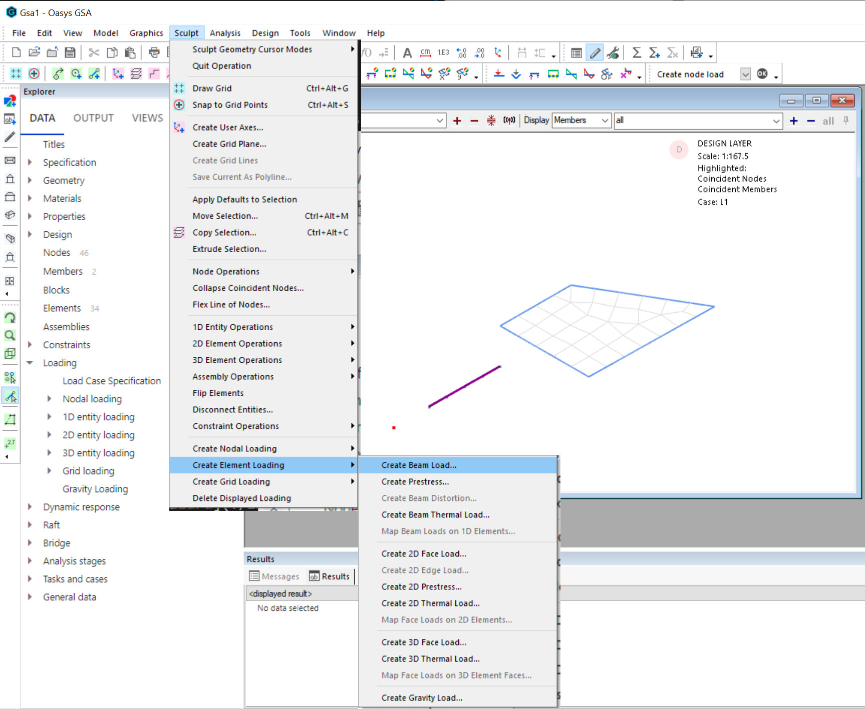
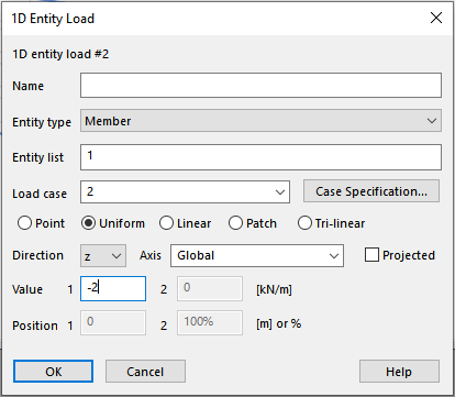
- Enter the load case, type, direction, axis and value then click OK to apply the load.
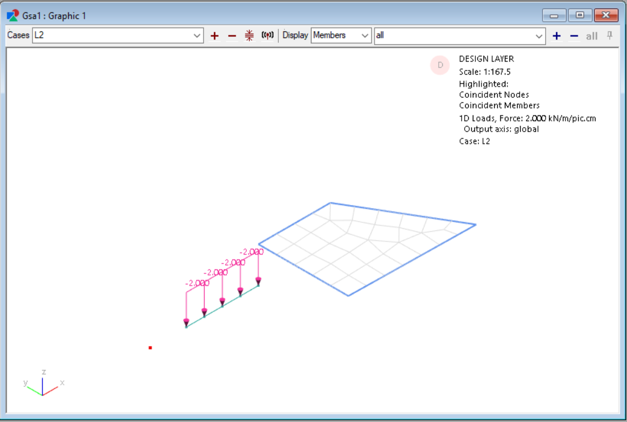
- Click on the Show load diagrams toolbar button to view the load.
Note: In order to apply and view the loads graphically, make sure that elements for the member have been created. To create elements from members, go to Model > Coordination tools > Create elements from members or use the toolbar button
.
Method 2: Apply beam load to a selection of members using the data table
-
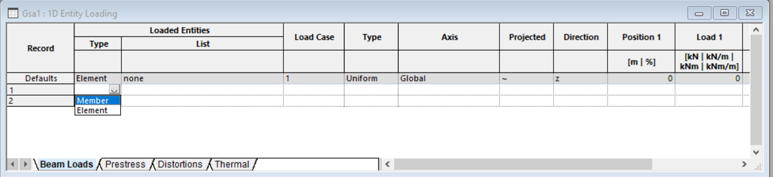
Go to Explorer pane > Data > Loading > 1D entity loading > Beam loads.
-
Select Members from the entity type dropdown.
-
Enter the 1D members you would like to apply the load to in the table.
Tip: You can load a list of members by specifying its ID, group or by list name. E.g., ‘1 to 5 25 26’, ‘G1’, 'list name'.
Note: 1D member loading should not be dependent on 1D properties if you are going to use the design functions. Running a design can modify the 1D property, so applying loads by referencing a property ID (for example, “PB1”) or including the property ID in the list name (for example, list name as “PB1 PB2”) can lead to the applied loads being changed, lost, or applied to different members.
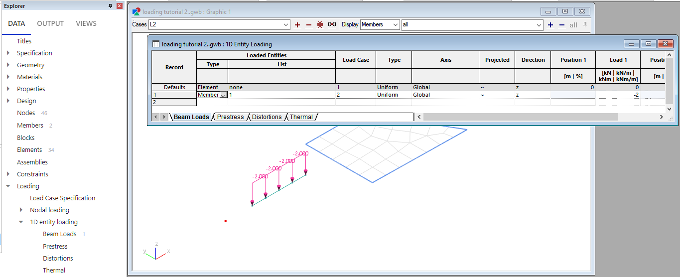
-
Specify your load case, type, axis, direction and magnitude.
-
Click on the Show load diagrams toolbar button
to view the load.
Note: In order to apply and view the loads graphically, make sure that elements for the member have been created. To create elements from members, go to Model > Coordination tools > Create elements from members or use the toolbar button
Apply other types of 1D entity loading
To apply loads to elements, follow a similar process but select Elements from the entity type dropdown.
To apply prestress, distortions and thermal loading, follow a similar process using the tables located under beam loading in the explorer pane.
2D entity loading
For 2D entities, you can apply loads to a member or an element. See the member and element loading explanation for more information on what each means.
The following steps show how to apply a face load to a 2D member. Similar steps can be taken to specify other 2D loads for members or elements.
-
Explorer Pane > Data > Loading > 2D entity loading > Face loads.
-
Double click the record number to bring up the face load wizard or modify the table directly to input load case, type, axis, direction and magnitude.
Note: You have the option to choose from uniform, variable, or point for type of loading.
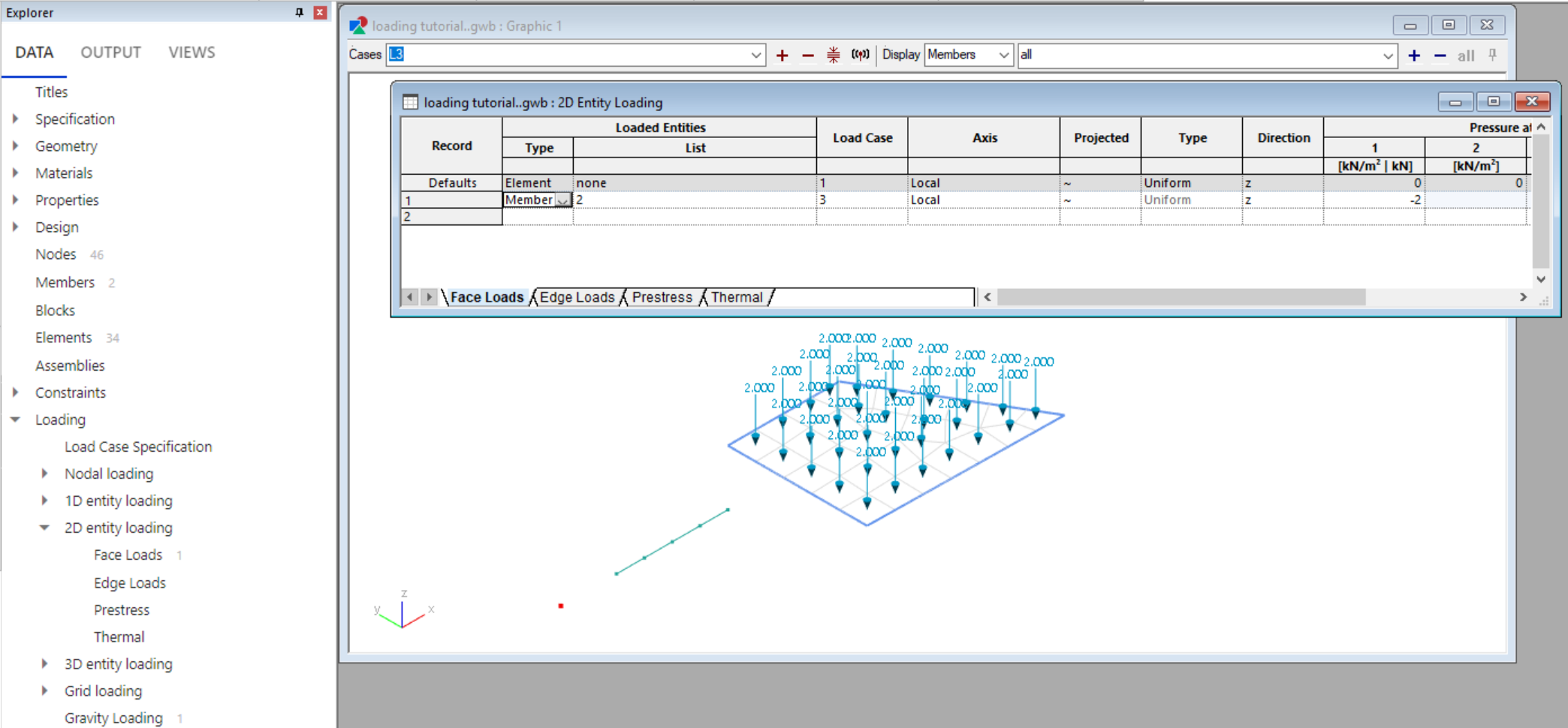
- Click on the Show load diagrams toolbar button to view the load.
Note: In order to apply and view the loads graphically, make sure that elements for the member have been created. To create elements from members, go to Model > Coordination tools > Create elements from members or use the toolbar button
To apply edge, prestress, and thermal loading, follow a similar process using the tables located under 2D entity loading loading in the Explorer pane.
3D entity loading
For 3D entities, you can apply loads to a member or an element. See the member and element loading explanation for more information on what each means.
The following steps show how to apply a face load to a 3D member. Similar steps can be taken to specify other 3D loads for members or elements.
-
Explorer pane > Data > Loading > 3D entity loading > Face loads.
-
Double click the record number to bring up the Face load wizard or modify the table directly to input load case, type, axis, direction and magnitude.
-
Click on the Show load diagrams toolbar button
to view the load.
Note: In order to apply and view the loads graphically, make sure that elements for the member have been created. To create elements from members, go to Model > Coordination tools > Create elements from members or use the toolbar button
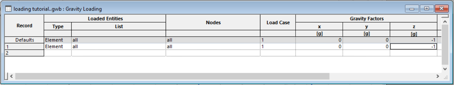
Gravity loading
-
Explorer pane > Data > Loading > Gravity loading.
-
Enter which entities and nodes you would like to apply an acceleration to in the table.
Grid loading
The following video shows how to add grid area loads to a surface and how to expand the load for checking purposes.
Oasys GSA - creating grid planes, surfaces, and area loads
See grid loads theory for more information on how grid loads are calculated.
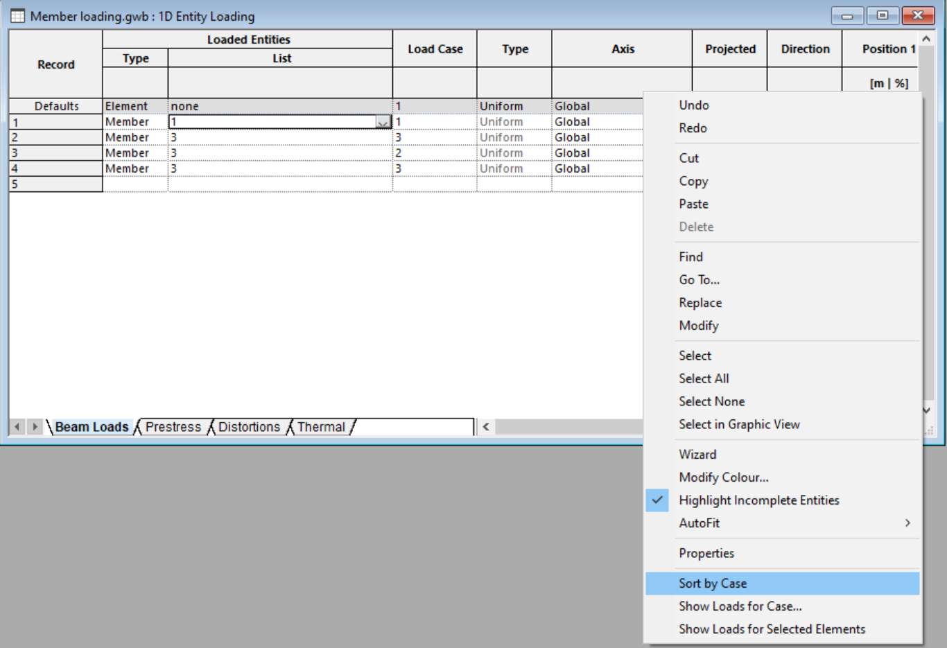
Sorting loads
You can sort load records by load case. Open the relevant load table, right click in the table and select Sort by case:
-
Explorer pane > Data > Loading > Load case specification.
-
Enter case type parameters in the Specification table.
-
When complete, open another loading tab from the Explorer pane.
-
Right click inside the table that opens and select Sort by case.