Model debugging
As analysis models often contain errors the first time they are run, it is important to understand what is causing the errors and how they can be resolved. It is ultimately the responsibility of the user to verify the validity of results and fix any modelling errors. In GSA, bugs are highlighted as either errors or warnings; both are explained below.
Errors
Within the analysis report, errors are highlighted in red. If errors are encountered in an analysis task, the model will not be analysed.
Most of the time, errors are caused by a lack of model stability (i.e., missing support conditions). Two categories of these stability issues are:
- Elements are poorly restrained or not properly connected to other elements.
- Elements are significantly more stiff than other elements in the model.
A general approach to resolve stability errors is described below:
- Read the analysis report and note the element(s) or node(s) referenced that are causing issues.
- Review nodal support conditions within the model (see tutorial on Label restraints).
- Check that support conditions are provided for the structure in all three translational axes (x, y, z).
- Check that support conditions are provided for the structure in all three rotational axes (xx, yy, zz).
- Review rigid connections and link elements (if applicable – see reference on Rigid constraints).
- Re-analyse the model.
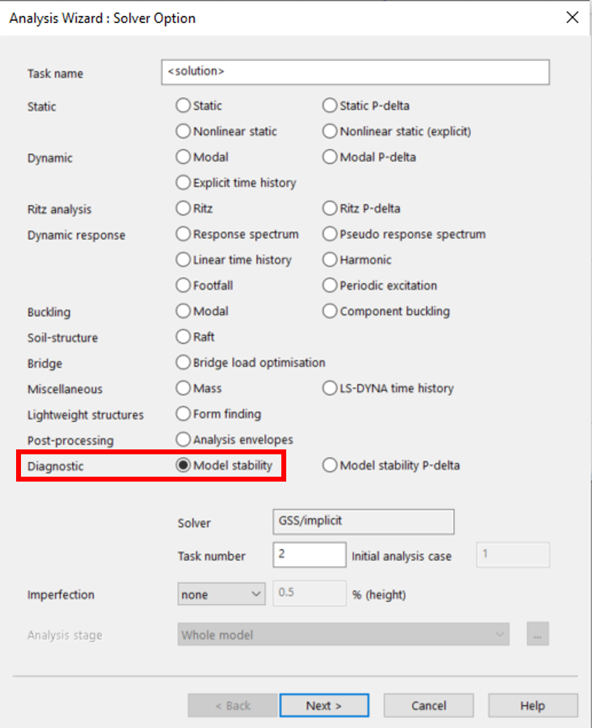
- If there are still errors, run a model stability analysis to diagnose further issues.
For more detailed information on the background behind ill-conditioned models, please refer to the GSA theory document.
Warnings
Within the analysis report, warnings are highlighted in blue. If warnings are encountered in an analysis task, the model will be analysed, but the results may not be accurate or practical. A list of common types of warnings (not exhaustive) is listed below.
1D Element to 2D element connection
To accommodate more load distribution between a 1D and 2D element (i.e., column to slab), rigid constraints can be added to the interface between the two elements. This can be done in the Design layer by checking the box under Properties Pane > Automatic offsets > Internal.
This adjusts the 2D element mesh based on the geometry of the 1D element. The 2D element mesh would then need to be redefined within the Analysis layer; refer to 2D members and meshing for a tutorial on this. This feature is enabled when angle between the 1D member's x axis and the 2D member's normal is less than 60 degrees.
Separate structures in model
If rigid constraints or link elements are being used in the model, sometimes they may not be set up correctly. In this scenario, the elements may not be properly connected to one another, resulting in no load transfer. Refer to the reference on Rigid constraints for more information on how rigid constraints and link elements can be used.
Properties not defined
There may be instances where some elements have not been assigned any properties. Refer to the tutorial on Member and element properties for details on how to create and assign element properties.