Steel design
The following video describes how to set up the steel designer in GSA including member optimisation using section pools.
Oasys GSA 10.1 - 2. Steel design
The following Tutorial will show you what variables to define, how to check results, and how to optimise your design.
1. Defining variables
1. Define design specifications
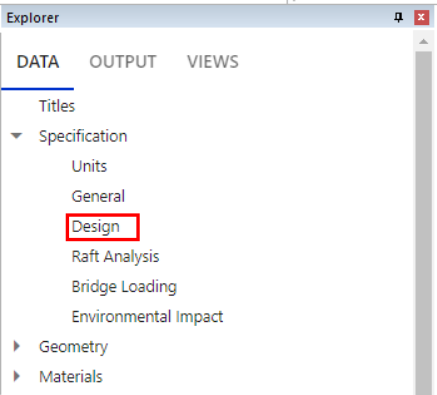
- In the Data tab of the Explorer pane select Specification > Design.
- Under the Design code dropdown, select the desired code.
- Under the Default steel dropdown, select the desired steel grade.
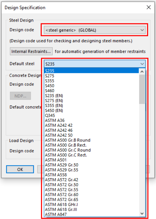
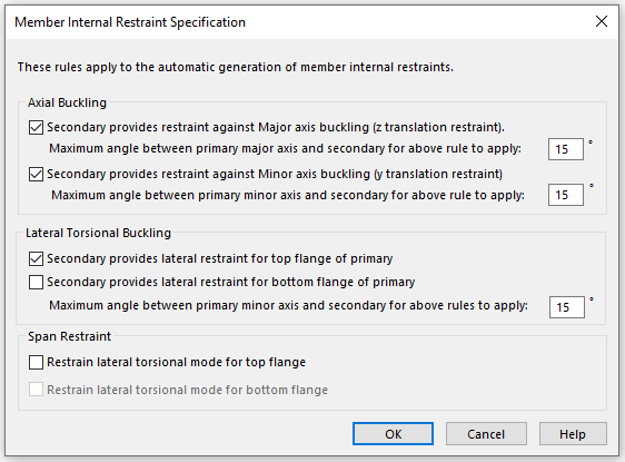
- Internal restraints can be used to customise the automatic generation of member internal restraint. To modify the default assumptions, go to Explorer pane > Data tab > Specification > Design and click on Internal restraints.
2. Define mterial properties for steel
In order to carry out steel design, the member's material must be defined by a steel material grade. The material grade contains both analysis information as well as design information such as its strength.
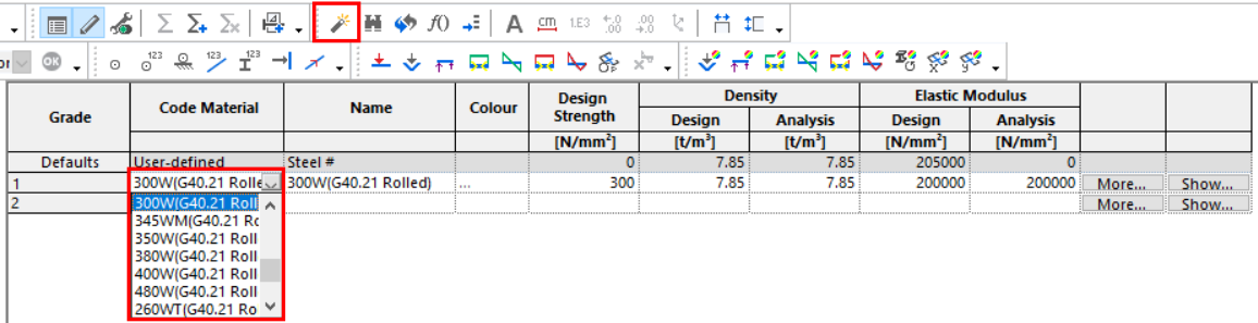
- In the Data tab of the Explorer pane select Materials > Steel.
- Add a steel material grade from the dropdown, or double click the row to open the Wizard
 and change the grade properties.
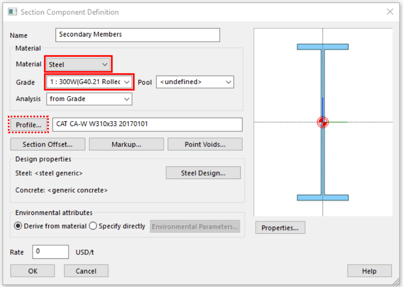
3. Define section properties
- In the Data tab of the Explorer pane select Properties > Section Library.
- Double click on an empty property row, or click the Wizard icon.
- Select a Profile for your section.
- Make sure the material type is Steel and the desired material grade is selected.
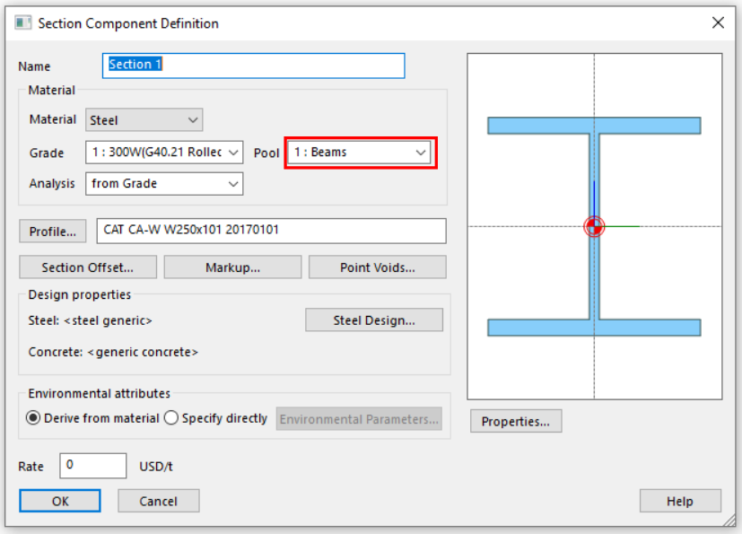
4. Define steel section pools
This step is optional and is only required if you wish to optimize the steel section using GSA.
The design feature can iterate through different steel sections for each member to select the most efficient section.
- In the Data tab of the Explorer pane select Design > Steel Section Pools.
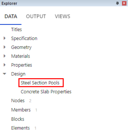
- Enter a descriptive name of your pool.

- To assign sections to your pool go to Properties > Section Library, and select a property.
- Open the Wizard, and choose your pool from the drop down.
Go to Steel Selection Pools for more information.
5. Define steel members
-
Model the structure in the Design layer with appropriate supports, releases, etc.
-
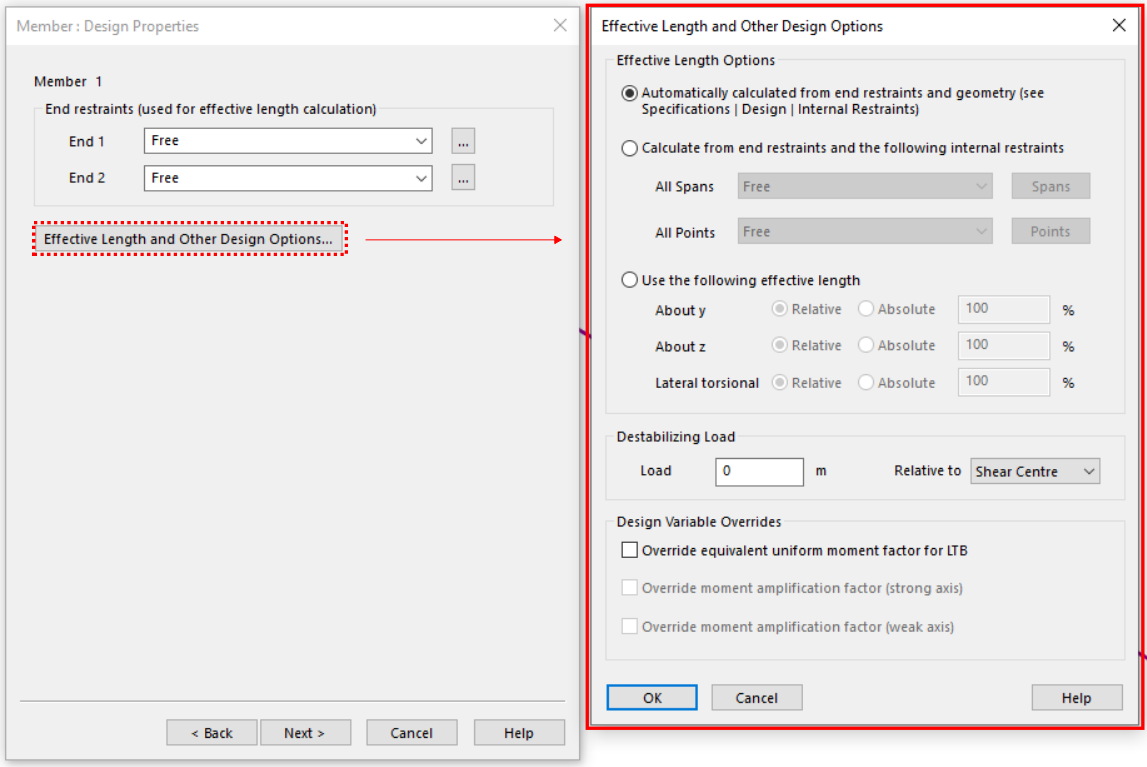
Define the effective length using either the Properties pane or the Wizard. See the Effective length calculation options on Member: Design properties for more information.
- Properties pane
- Select a steel member.
- In the Properties pane, member properties will be displayed.
- Scroll to the bottom of the Properties pane
- Select calculation methods from the drop down menus.
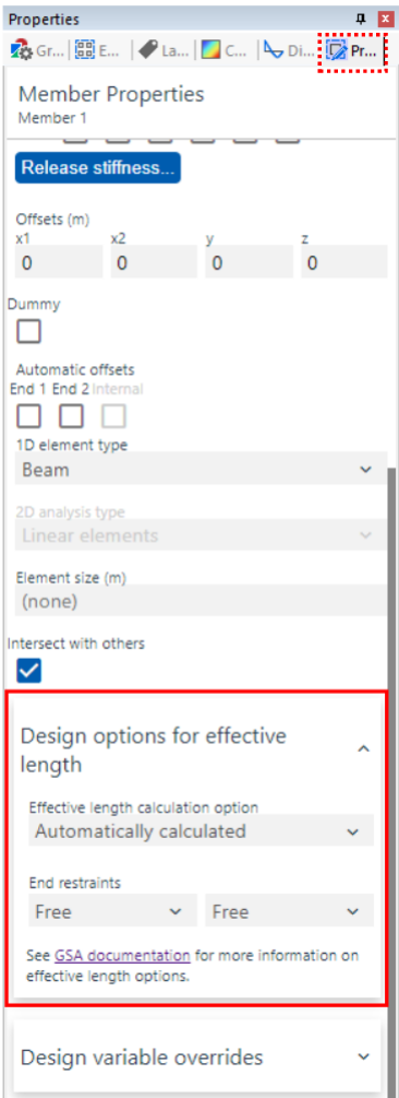
- Select the appropriate method for calculating effective lengths and define the end restraints.
- Wizard
- Double click on the member, it will take you to Member : Definition
- Click Next to go to Member : Design Properties
- There you can change the end restraints.
- Select Effective Length and Other Design Options for more options.
- Properties pane
-
Design variable overrides (optional). See the Design variable overrides on Member: Design properties for more information.
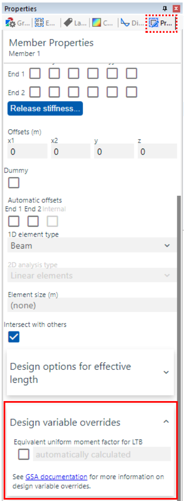
- Properties pane
- Select a steel member.
- In the Properties pane, member properties will be displayed.
- Scroll to the bottom of the Properties pane
- Check the Equivalent uniform moment factor for LTB box or any other variable you would like to override and enter a value to override the automatic calculation.
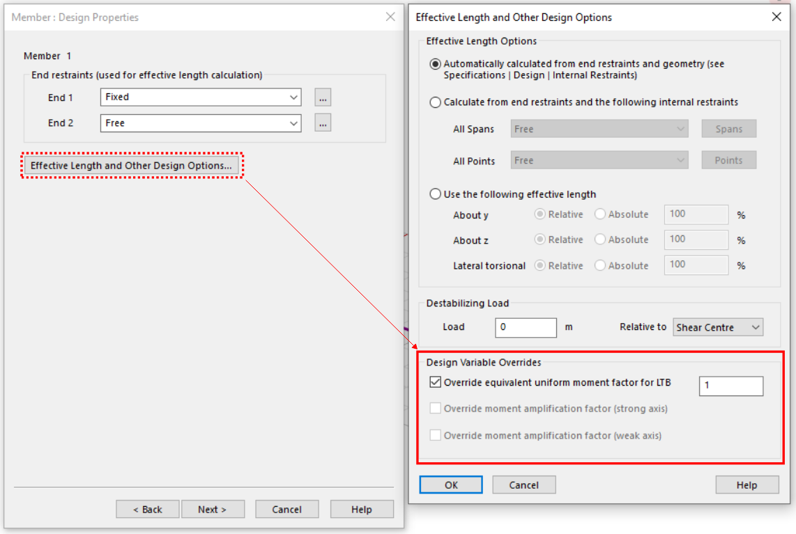
- Wizard
- Double click on the member, it will take you to Member : Definition
- Click Next to go to Member : Design properties
- Select Effective Length and Other Design Options.
- Check the Equivalent uniform moment factor for LTB box and or any other variable you would like to override enter a value to override the automatic calculation.
- Properties pane
2. Checking the steel design
There are two ways to run the steel designer:
- Option 1: By running a design task which saves the results to user module
- Option 2: By completing a quick check on a set of members which calculates the results when requested.
Option 1: Using a design task
-
Ensure your model has an analysis run.
-
Set up a design task.
- Go to Design > New design task to open the design task Wizard.
- Name the task
- Select Steel 1D members for the design option
- Select a list of members for which you want to carry out design.
- Select the desired combination case
- Select Check
-
View overall utilization results
- View a summary of design by going to Output > Global Results > Steel Design Synopsis.
- View the overall utilisation for each member in the design task by going to Output > User Modules > Member User Module. You can also contour this result by going to Contour settings > User modules > Member user module.
Note: user modules saved with the model will remain there even if the analysis is erased and user has made changes to the model. To update the user module based on the most current data, please re-run the design task.
- View other results and step-by-step calculations. There are two ways to examine your results, using contours or outputs.
- Contours
- Ensure that you are in the Design layer (use shortcut: Ctrl-Alt-D to switch between layers if necessary) and that the members of interest are in your current Graphic view.
- Select the desired analysis case is selected in the top toolbar.

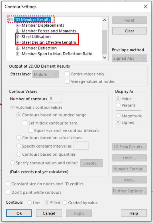
- Select Contours
 icon.
icon. - Select 1D Member Results, and then any of the options under Steel Utilisation or Steel Design Effective Lengths to contour the desired results.
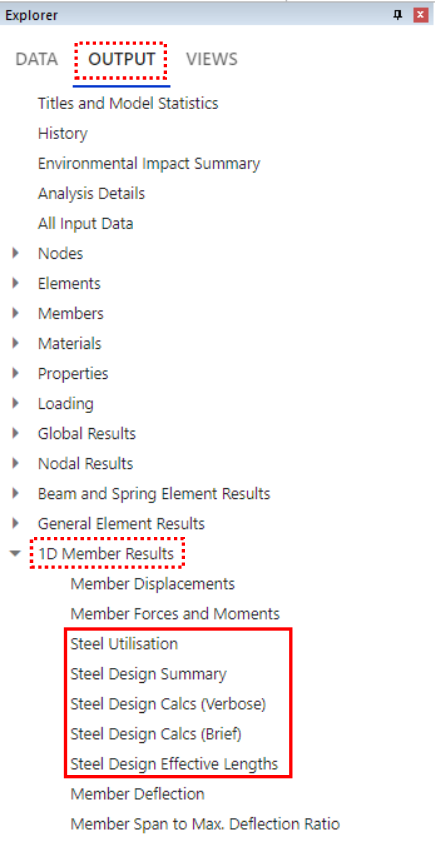
- Outputs
- Use the entity selection tool to select the members for which you want to view results.
- In the Output tab of the Explorer pane, select 1D Member Results.
- Select any of the steel designer options to view the tables of results. Either Steel Utilization, Steel Design Summary, Steel Design Calcs (Verbose), Steel Design Calcs (Brief), or Steel Design Effective Lengths.
- Contours
Option 2: On-demand checks on members
- Ensure your model has an analysis run.
- Follow step 3 from option 1.
3. Optimizing the steel design
- Ensure steel section pools are set up (see step 1.4).
- Define a steel design task by going to Design > New design task. Ensure that the target utilisation ration and design objective are defined.
- Under Steel design select Grouped design if you want members in the same pool to be assigned to the same section.
- Select Design.
Running design will update the member property to one of the sections in the section pool. The section that most effectively meets the design objective will be chosen.
Note: the analysis model and design model may be out of sync. At this point, it is advised to update the elements from members to re-analyse the model with the updated sections and re-check the design.