Staged Analysis
AdSec 10.0 can analyse the effects of adding additional structure to sections that are already loaded. In conducting a staged analysis, one must ensure that the deformation from the originally loaded section is transferred to the next stage which has additional structure added. This is done to capture any load or deformation that becomes locked in at the time of constructing the next stage.
The deformation is considered to be locked-in and transferred from one stage to the next. Deformations are extracted from ULS and SLS analysis from the previous stage and are applied to the respective analysis of the next stage. For interpolated SLS tension model, ULS, SLS cracked and SLS uncracked deformations are extracted and carried forth to the next stage.
For example, consider a situation where you are modelling a reinforced concrete beam that is un-propped before the slab is cast on top. To do this you would create a section with two components in AdSec 10:
1) a beam section with an offset such that it stops at the slab soffit;
2) a slab section.
Note that any or all components can be offset from the origin. Forces are assumed to apply at the origin.
Procedure for staged analysis:
1) Create a task, say Task 1 defined with Load input having only Component 1 (the beam) been enabled.
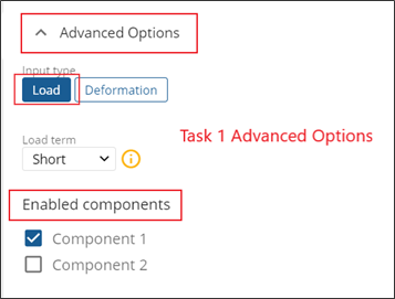
2) 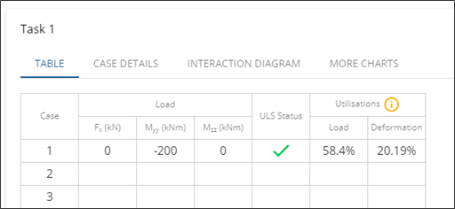
Create a case, say, Case 1 with a Load input of Moment M~yy~= -200kNm, equal to the load on the beam in the first stage.
3) 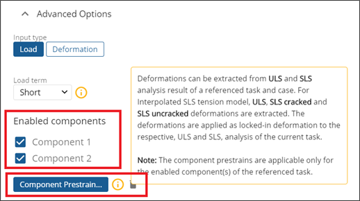 Create a new task, Task 2, having both the components enabled.
4) Click on Component pre-strains... button and enter referenced parameters as Task 1 and Case 1. This will extract the component ULS and SLS deformation of the respective enabled components of the preloaded task.
5) 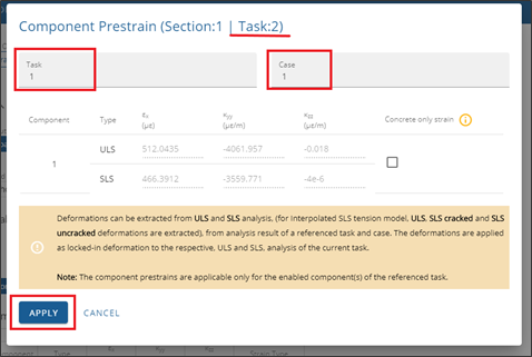
Click on Apply, the task shall be re-analysed to incorporate the component pre-strain parameters.
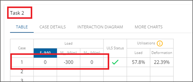
6) To get results for the load/deformation for the preloaded task, create a new case in the preloaded task, Task 2, with loads equal to the total load on the combined section.
a. If the *Task 2* input type is load, the input should be the total load. In the case of the example, load input *M~yy~ = -300kNm* means *-100kNm* additional load plus *-200kNm* (*Case 1 of Task 1*) due to the component pre-strain.
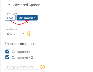
b. If the *Task 2* input type is deformation, the additional deformation can be directly entered, and the respective pre-strain deformation will be added for the ULS and SLS analysis.
This method also works, for example, for strengthening existing in situ beams, columns, and slabs with steel or carbon fibre plates.
How to use custom deformation as pre-strain?
Create a new task, say task 1.
Change the input type to Deformation.
Enter a case, say, Case 1 with desired deformation values in the table. This deformation will be added as locked-in deformation to the subsequent task for both ULS and SLS analysis.
Create a new task, say Task 2.
Click on Component pre-strains... and enter referenced parameters as Task 1 and Case 1. This will pre-strain the components with the Applied Deformation of Case 1 values.
Click Apply.
Reference point for the component pre-strain:
If the elastic centre (where any specified forces are applied at this point) of the preloaded components shifts due to the additional enabled components between the referenced and preloaded tasks, the deformation extracted from earlier stages will not be appropriate for those that follow i.e., the deformation to be corrected by the product of the curvature and the offset between the two reference points.
Note that when the preloaded components are loaded by an axial force, the shift in reference point will require a moment equal to the product of the axial force and the offset to be applied.
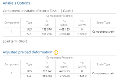
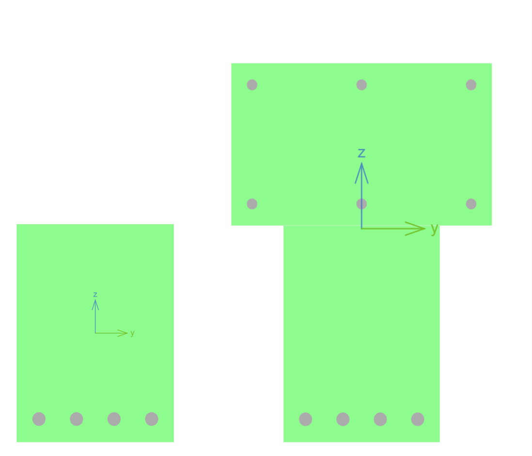
Example: Assume a beam with dimensions 400x300 mm with a reference point at the elastic centre of the beam, in a referenced task (say Task 1) and the beam with a slab of dimensions 300x500 mm is used in a preloaded task (say Task 2). While applying the component pre-strain to the compound section, the pre-strain deformation of the beam is adjusted to account the shift of the reference point (elastic centre shifted upwards by approximately 194 mm).
If the deformation of the beam in the referenced task (Task 1) is as given in Table 1, the deformation is adjusted to the elastic centre of the combined section in the preloaded task (Task 2) as given in Table 2. These two tables can be accessed from the Case Details of a preloaded task.