1D elements
This entry provides a summary of 1D elements found in GSA. For a more detailed guide, see our references entry on element types.
Type
The main types of 1D elements in GSA include:
| Element | Type |
|---|---|
| Bar | A two-noded element with axial stiffness only. A bar can sustain compression and tension forces. |
| Beam | A two-noded element that models axial, bending and torsional effects. |
| Cable | Tension-only elements. They can be normal or sliding. |
| Damper | A two-noded element with no stiffness. It does not contribute in static analysis but is defined by dashpot constants providing viscous damping. |
| Link | A two-noded element which links two nodes rigidly in the directions specified in the Link properties module. |
| Rod | A two-noded element, similar to a bar, but with torsional stiffness. |
| Spacer | For use only in soap-film form-finding analysis. They control the position of nodes on the surface that is formed. |
| Spring | A two-noded element in which stiffnesses are specified explicitly rather than derived from geometrical properties. |
| Strut | A two-noded element with axial stiffness only. A strut has zero stiffness under tensile forces. |
| Tie | A two-noded element with axial stiffness only. A tie has zero stiffness under compressive forces. |
Releases
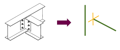
End releases are defined at the ends of the member or element in term of its local axis.
As with nodes, there are six degrees of freedom for a typical beam member or element.
The example below shows a rotationally stable connection with rotation released about the local and axis of the member or element (indicated in the image below by cross-hairs).
Orientation
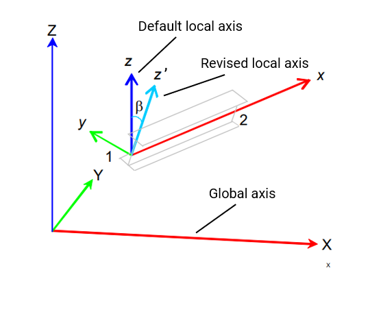
Orientation is used to alter the local axis of an element from the default. For non-vertical members and elements, the default local axes are defined so that the local z axis aligns with the global z axis.
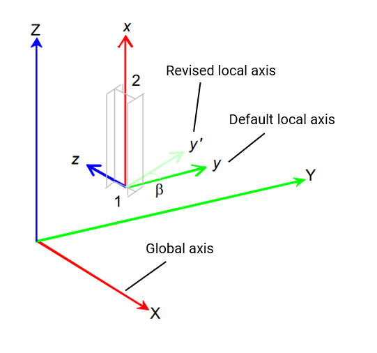
For vertical members and elements, the default local axes are defined so that the local y axis aligns with the global y axis.
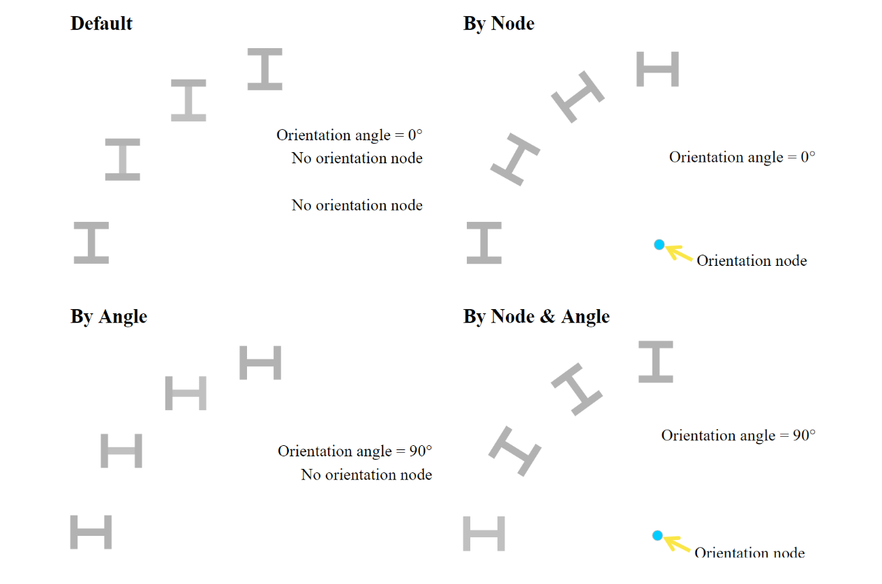
The orientation angle (Beta) is used to define the rotation of the member or element y and z axes from their default positions about the element x axis.
Non-vertical members:
Vertical members:
In GSA, you can choose either an orientation node or orientation angle to specify the member or element orientation.
Offsets
Element offsets are specified in the local element axis.
They can be defined by a set distance, or to the face of another object.
Vertical and horizontal offsets are related to the centroid of the element, while edge offsets are related to two end nodes of the element.
Edge offsets to model beam to column connections

Vertical and horizontal offsets to model a composite or edge beam
