Element Types
Beam Elements
A beam element is a two-noded element that models axial, bending and torsional effects. Shear deformations are included when calculating deflections, but can be excluded by setting the shear area factors to 0. The orientation of a beam is defined by its topology, an orientation node and an orientation angle as described in the Axes section. Releases allow some of the degrees of freedom to be treated as pinned. If all the rotational degrees of freedom are to be considered as pins it is preferable to use a bar or rod element. Offsets can be applied to beam elements where the flexible part of an element has to be offset from the node position.
Bar and Rod Elements
A bar element is a two-noded element with axial stiffness only. A bar can sustain compression and tension forces. The orientation of bars is the same as for a beam element with an orientation node and angle. Releases and offsets are not allowed.
A rod element is similar to a bar element but also includes torsional stiffness. The orientation of rods is the same as for a beam element with an orientation node and angle. Releases and offsets are not allowed.
Tie and Strut Elements
A tie element is a two-noded element with axial stiffness only. A tie will have zero stiffness under compressive forces.
A strut element is a two-noded element with axial stiffness only. A strut will have zero stiffness under tensile forces.
If a modal analysis is requested the model must behave linearly. In this case tie and strut behaves exactly like a bar element.
Spring Elements
A spring is a two-noded element in which stiffnesses are specified explicitly rather than derived from geometrical properties. The orientation of a spring is defined in the same way as a beam element with the x axis along the damper and the y and z directions defined by an orientation node and/or orientation angle. For a zero length spring the orientation is defined by the constraint axis of the first node.
In general a spring is defined by a stiffness, but there are variants on the springs, defined by the spring properties, that allow more specialized behaviour.
Quad and Triangle Elements
The quad and triangle elements are planar 2D elements. Quad elements can be either linear, with four nodes, or quadratic, with 8 nodes (four corner nodes and four 'mid-side' nodes). similarly the triangle elements can be either linear, with three nodes, or quadratic, with 6 nodes (three corner nodes and three 'mid-side' nodes). For plane stress, plain strain or axisymmetric structure types these are limited to acting purely in the plane of the element, but in a space structure, these can act both in-plane and out of plane (in bending).
For the nonlinear static solver, only the linear variants can be used. In this case the solver converts each quad element during the analysis into four triangular elements by creating an additional 'node' in the centre of the quadrilateral.
There are two methods for their out-of-plane formulation (Mindlin or MITC) and two methods for in-plane behaviour (Bilinear or Allman-Cook). See the Advanced Solver Settings for more details on the differences. The in-plane variants apply only to linear elements.
The quadratic elements have greater accuracy that the linear elements, but at the expense of a larger model. Quadrilateral element provide greater accuracy that triangular elements.
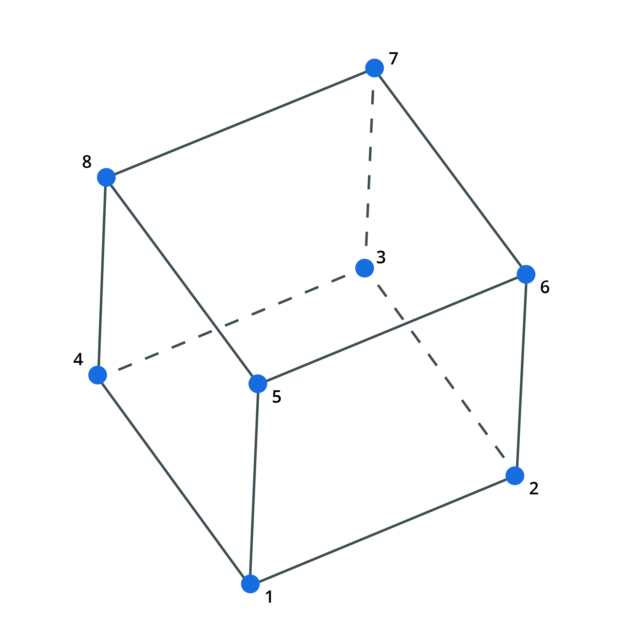
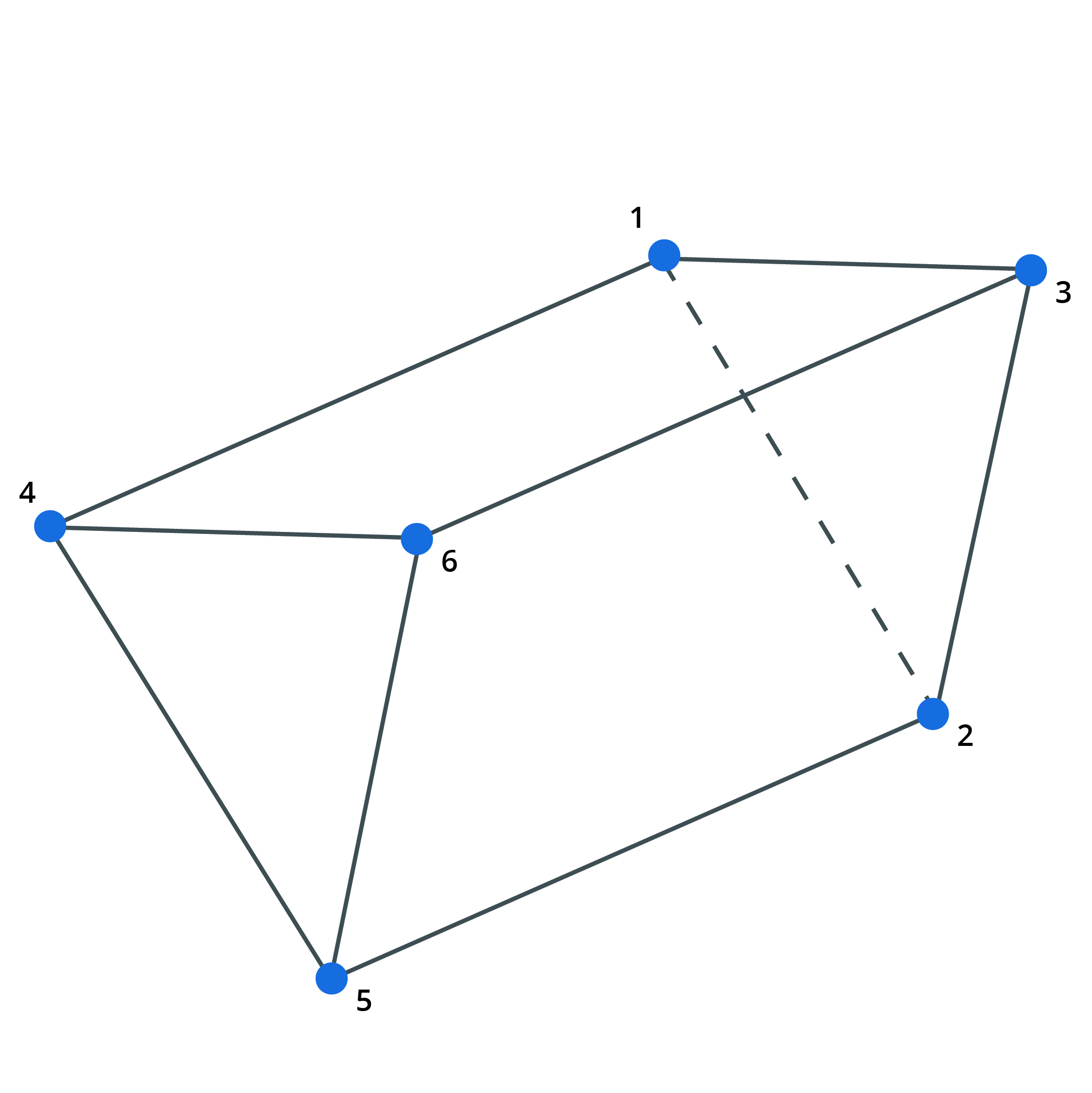
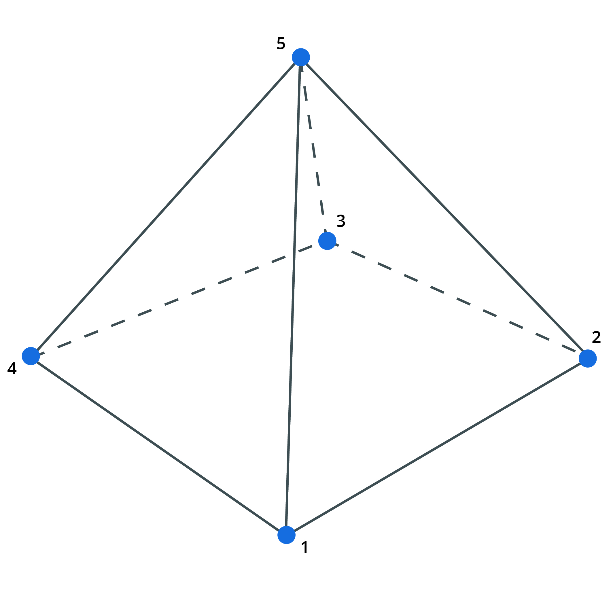
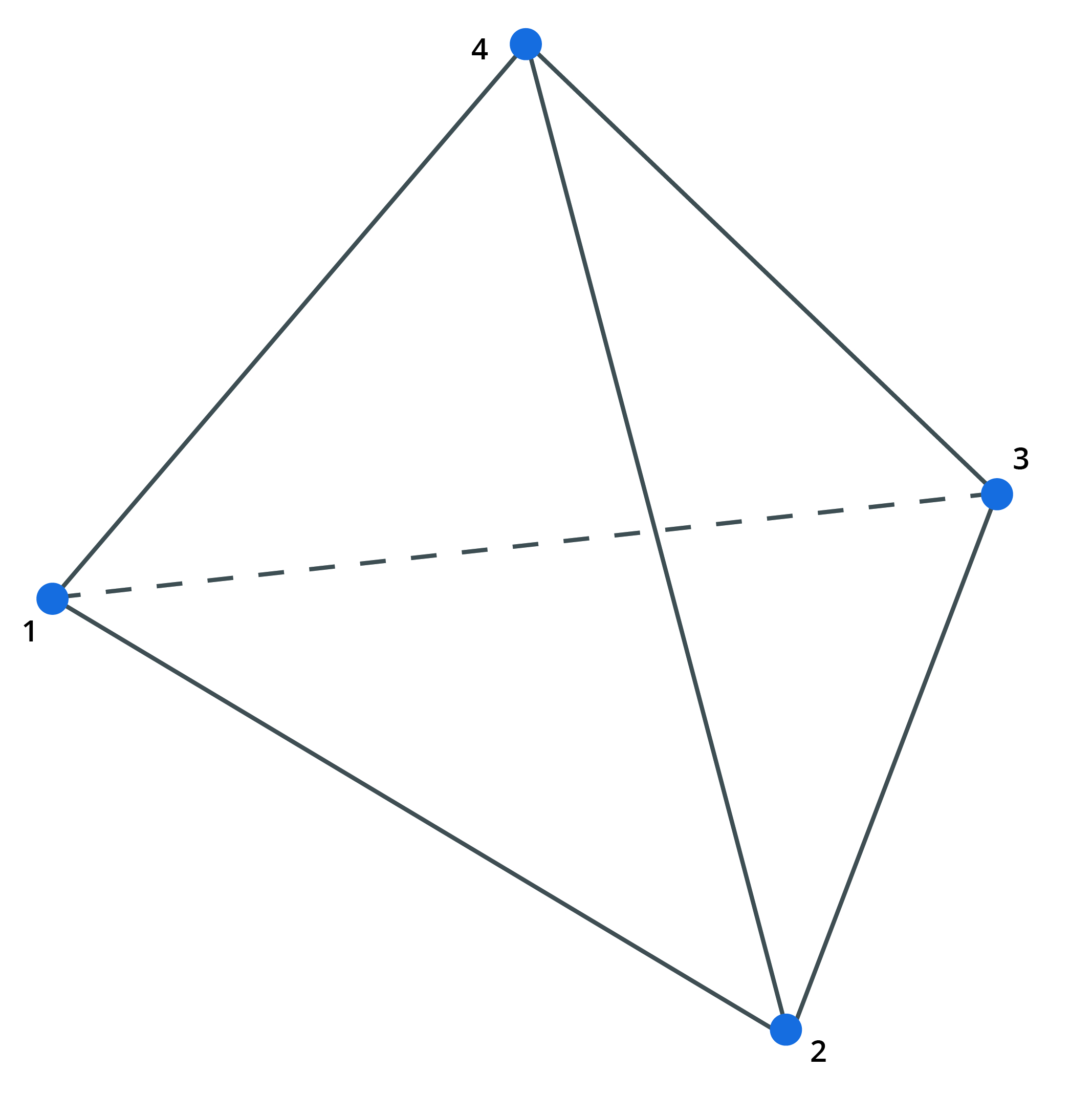
Brick, Wedge, Pyramid and Tetra Elements
Brick, wedge, pyramid and tetra elements are 3D elements defined by 8, 6 5 and 4 nodes respectively. They can be used for modelling any three dimensional item. They can be used in all analyses except nonlinear static.
Infinite brick and wedge elements are defined by one face which then stretches in an infinite direction in an orthogonal axis.
Link Elements
A link is a two-noded element which links two nodes rigidly in the directions specified in the Link Properties module. The element is assumed infinitely stiff in the link direction. Most link types preserve equilibrium but in the case of a custom link the same restriction apply as for a joint and equilibrium is not enforced.
See also Link elements and rigid constraints.
Cable Elements
Cable elements are tension-only elements. The way these elements work depends on whether they are set to be "normal" or "sliding" in the cable property options.
Normal Cables
A normal cable behaves like a tie element in all analysis types, only the properties are specified differently.
Sliding Cables
Sliding Cables are treated as Normal Cables in all analysis types except for GsRelax (Nonlinear static, Form finding, and Component Buckling).
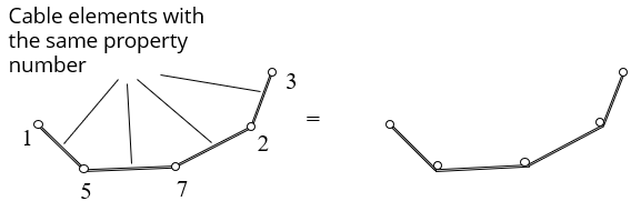
In a GsRelax analysis sliding cable elements model a multi-noded cable chain where the tension is constant along the entire cable chain. This means that the cable can slide over the intermediate nodes and only cable change of direction will result forces being transferred to intermediate nodes.
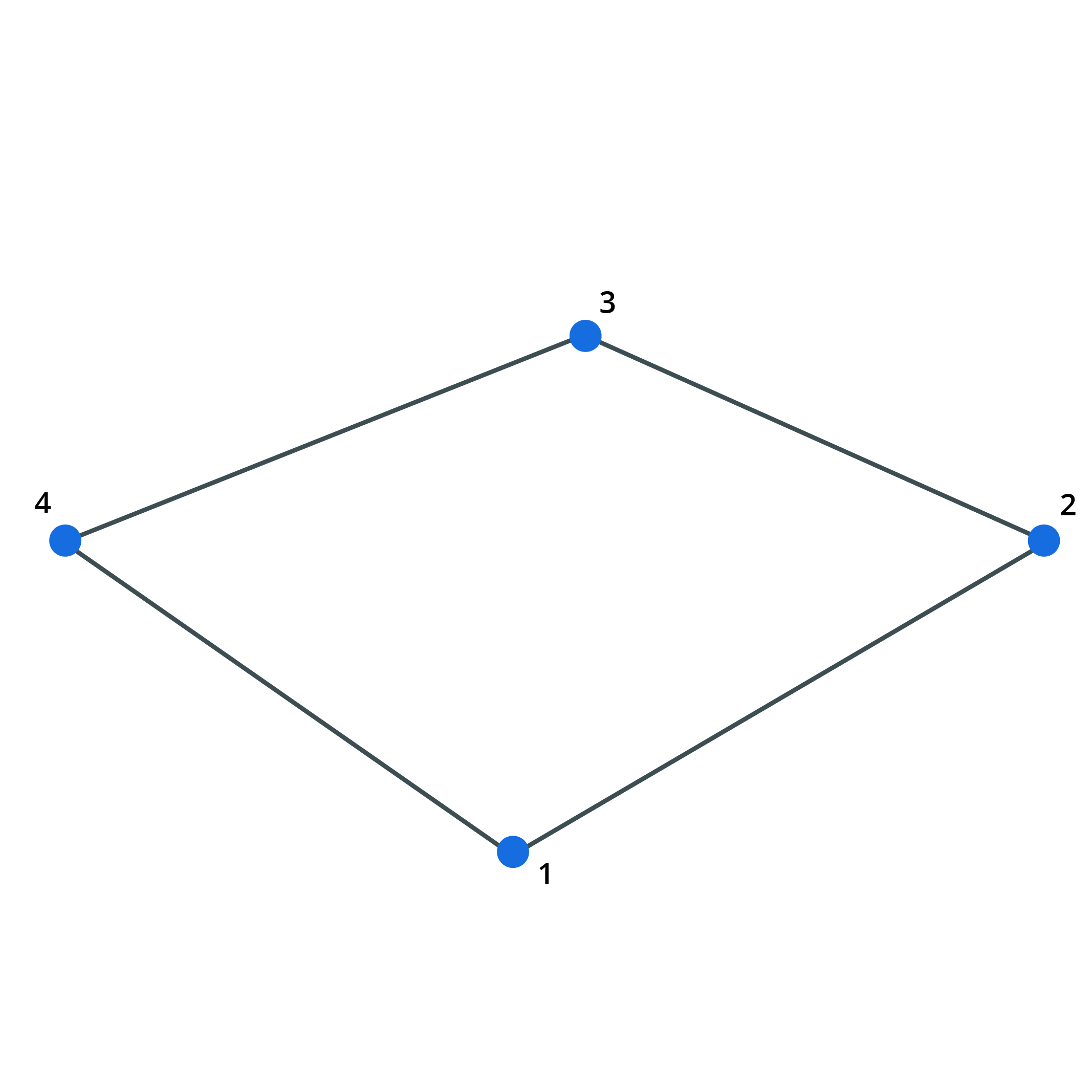
To define a sliding cable, add a number of cable elements with the same property number in a continuous chain. A cable cannot be branched. Each individual cable chain must have a unique property number. An single sliding cable element will behave as a tie.
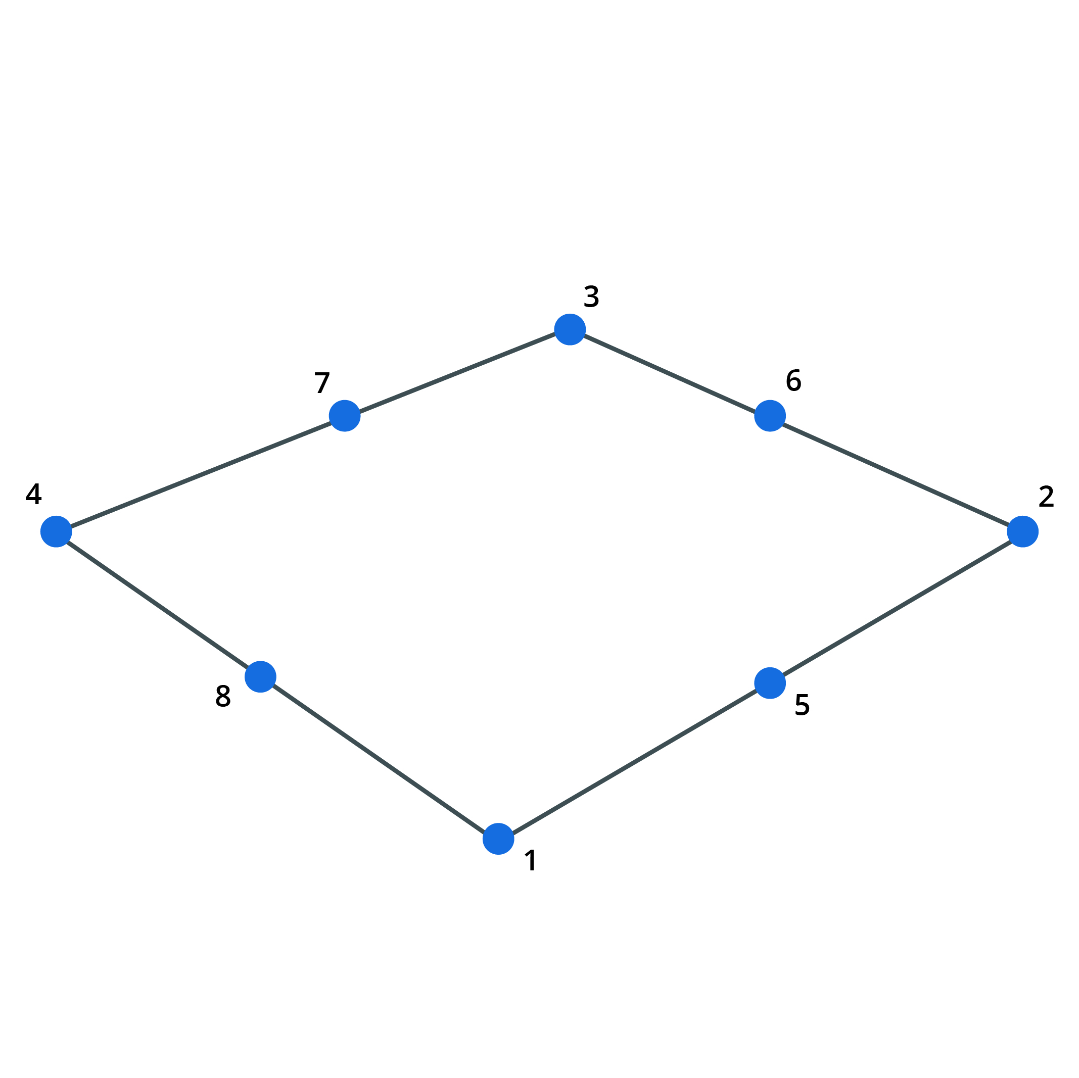
 (Acceptable sliding-cable)
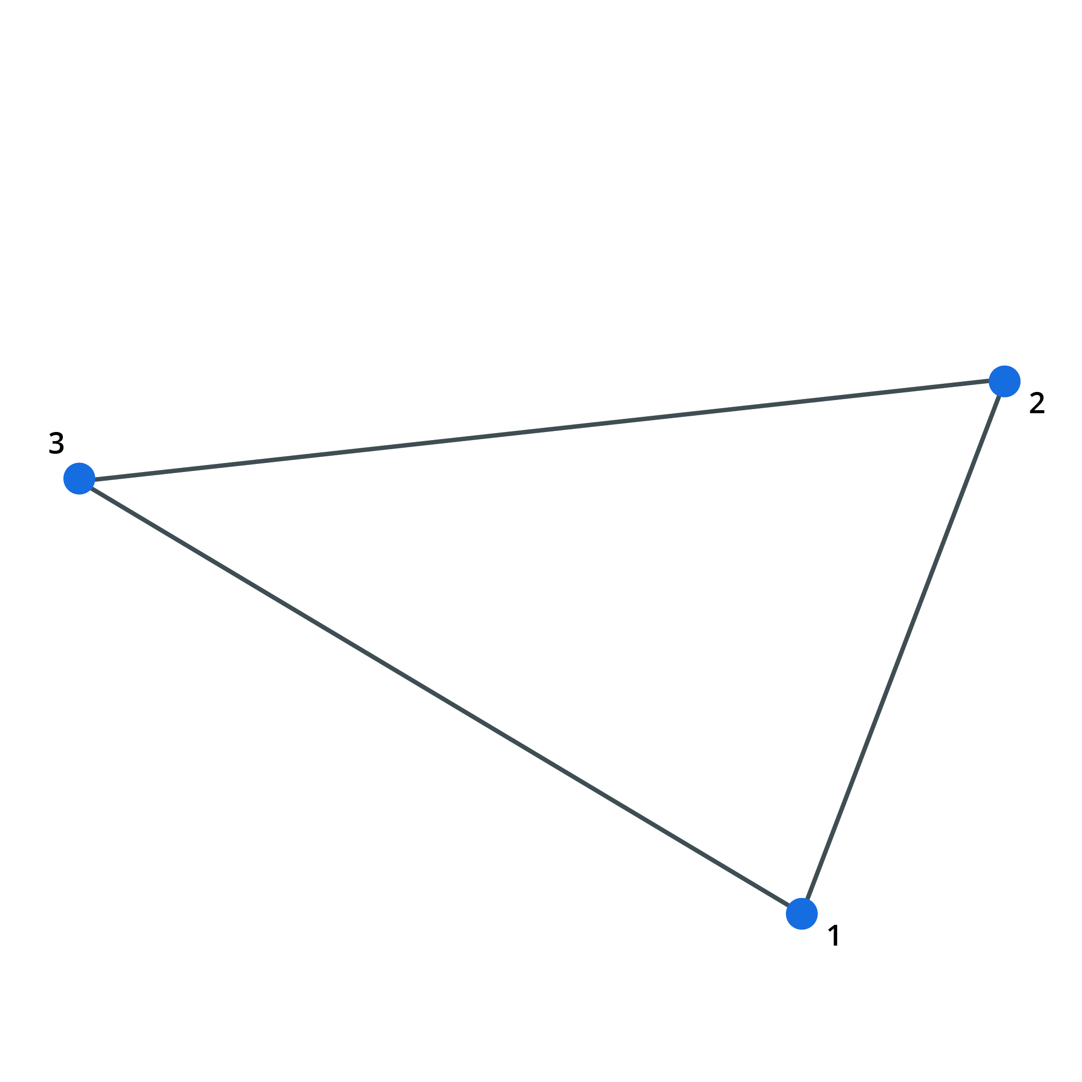
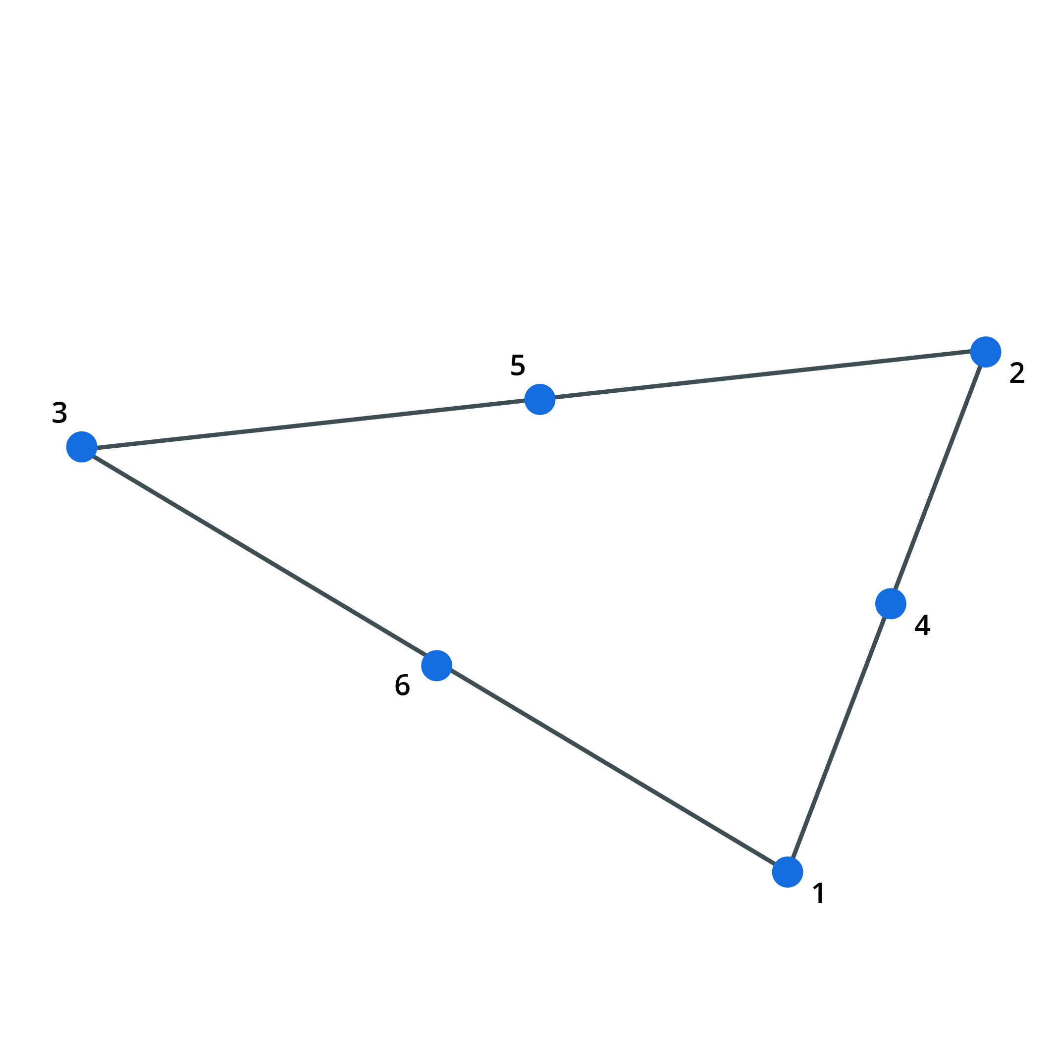
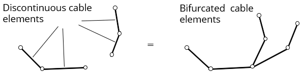 (Unacceptable sliding-cable)
For more information see Cable Properties
Damper Elements
A damper is a two-noded element with no stiffness, so it does not contribute in static analysis. Instead it is defined by dashpot constants providing viscous damping. The orientation of a damper is defined in the same way as a beam element with the x axis along the damper and the y and z directions defined by an orientation node and/or orientation angle. For a zero length damper the orientation is defined by the node constraint axis of the first node. The damper characteristics are defined in the damper properties.
Spacer Elements
Spacer elements are only for use in soap-film form-finding analysis with the GsRelax solver. Spacer elements are ignored by the Gss solver. Each Spacer chain joins a line of nodes and is, in effect, the opposite of the sliding Cable element. Spacer behaviour is described in detail in the Form-Finding theory section. Spacer chains do not apply any force to their nodes in a direction normal to the surface of the adjoining triangles and quads. Spacers therefore do not affect the surface that is form-found; they only control the position of nodes on the surface that is formed. Spacer chains do not exert any force onto the end nodes of the chain. Because of this, an isolated Spacer element will have no structural effect. To define the multi-noded Spacer chain input a list of 2 noded individual spacer elements with the same property number. Each individual spacer chain must have a unique property number. The program connects individual elements together to form a continuous chain of linked elements by linking common node numbers. A spacer cannot be branched.