
# LS-DYNA
# GSA to LS-DYNA
While GSA provides a powerful tool for structural modelling there are times when more powerful analysis is required. In such cases it can be useful to run the analysis on LS-DYNA. LS-DYNA is widely used for problem in mechanical engineering but has powerful features that are suitable for advanced structural analysis.
In general, creating a new LS-DYNA model from the GSA model gives scope for data to be missed and for the GSA and LS-DYNA models to get out of sync. The idea behind the GSA to LS-DYNA link is to allow the engineer to carry out the definition in a GSA reference model and to create a lightweight LS-DYNA model (keyword file) for analysis. If this model is ‘ready to run’ in LS-DYNA, then when changes are made to the GSA model it is straightforward to discard the LS-DYNA model and simply create a new model.
# LS-DYNA model in GSA
The GSA model is seen as the primary model however this can lead to problems where an LS-DYNA analysis required features or materials that are not used I a GSA analysis. Several features in GSA allow the engineer to define this extra data. The three key features are:
- LS-DYNA analysis task
- LS-DYNA materials
- Composite 2D elements
# GSA to LS-DYNA workflow
The way the link is intended to work is to:
- set up a model in GSA
- add extra modules such as DYNA materials
- create an analysis stage to map the GSA sections and materials to DYNA sections and material
- create an LS-DYNA analysis task specifying the relevant DYNA control parameters
- create a ‘ready to run’ DYNA keyword file.
# Data transferred to LS-DYNA
The link should be able to transfer:
- control information
- nodes
- elements – beams, shells, 3D, springs, dampers, masses
- axis sets
- properties - sections, 2D properties (including composite), 3D properties, springs, dampers
- rigid constraints (diaphragms)
- joints
- loads – nodes, beams, shells
- load curves
- sets – nodes, beams, shells
# Creating an LS-DYNA model
There are several features that make it easier to define the model for an LS-DYNA analysis.
# Materials
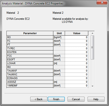
To create LS-DYNA specific materials use the analysis material wizard and select the include LS-DYNA material models option
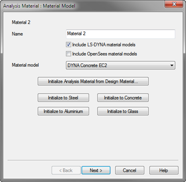
This leads to a page where the data to define the model can be entered. All parameters are defined as in the LS-DYNA Keyword Manual.
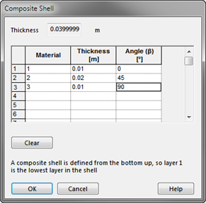
# Composite Shells
To define a composite shell: use the 2D property wizard and select the LS-DYNA Composite button to define the lay-up of the composite
The way we have implemented the link is to let the engineer set up a DYNA analysis task and the “run” option will create the keyword file.
# Analysis stages
The most convenient way to map between the GSA and LS-DYNA models is to used analysis stages and in-particular analysis stage properties or analysis stage materials. This allows the LS-DYNA materials to replace the normal GSA materials for an LS-DYNA specific stage.
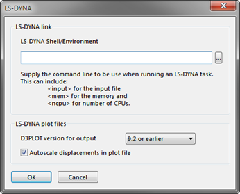
# LS-DYNA preference
The LS-DYNA preferences available from Preferences | Miscellaneous allow a default LS-DYNA environment to be specified. This can give the command line for running a LS-DYNA preprocessor such as LS-PrePost (opens new window) or Oasys PRIMER (opens new window).
# LS-DYNA analysis task
The final stage is to create an LS-DYNA analysis task. From the analysis wizard select the LS-DYNA task option and the appropriate analysis stage. This allows the definition of the LS-DYNA analysis, selecting the excitation type and output options for both plot and time history files.
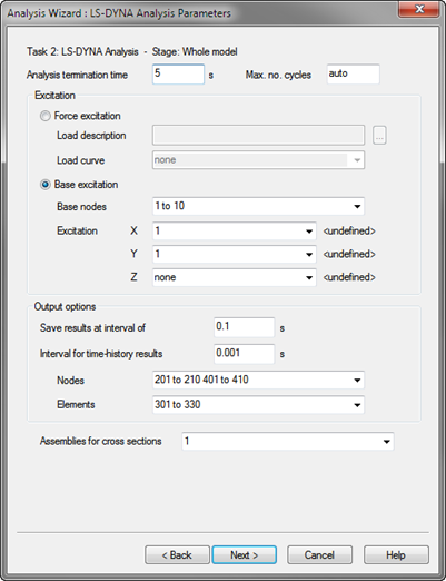
The subsequent page defines how the mass is to be assigned to the model. In GSA loads can be considered as additional mass. If this is required for the LS-DYNA analysis the export of the keyword file will include nodal masses corresponding to those that GSA would generate.
Damping can include either damper elements, Rayleigh damping or both.
The final page prompt for the file name for the keyword file and the command line to run on finish. If no command line is supplied the keyword will be still be written but GSA will not try to do anything with the file.
# Supported Keywords
# General
*TITLE
*CONTROL_TERMINATION
*DATABASE_BINARY_D3PLOT
*DATABASE_BINARY_D3THDT
*DATABASE_BINARY_INTFOR
*DATABASE_BINARY_D3DUMP
*DATABASE_BINARY_RUNRSF
*DATABASE_HISTORY_NODE
*DATABASE_HISTORY_BEAM
*DATABASE_HISTORY_DISCRETE
*DATABASE_HISTORY_SHELL
*DATABASE_HISTORY_SOLID
*DAMPING_GLOBAL
# Model
*DEFINE_COORDINATE_SYSTEM
*NODE
*DEFINE_COORDINATE_NODES
*BOUNDARY_SPC_NODE
*ELEMENT_BEAM
*ELEMENT_BEAM_OFFSET
*ELEMENT_DISCRETE
*ELEMENT_MASS
*ELEMENT_INERTIA
*ELEMENT_SHELL
*ELEMENT_SOLID
# Materials
*MAT_ELASTIC
*MAT_PLASTIC_KINEMATIC
*MAT_ORTHOTROPIC_ELASTIC
*MAT_FABRIC
*MAT_CONCRETE_EC2
*MAT_STEEL_EC3
*MAT_HYSTERETIC_BEAM
*MAT_HYSTERETIC_REINF
*MAT_PLASTIC_KINEMATIC
*MAT_PARK_ANG_BEAM
*MAT_GENERAL_NONLINEAR_6DOF_DISCRETE_BEAM
*MAT_SEISMIC_ISOLATOR
*MAT_RIGID
*MAT_LINEAR_ELASTIC_DISCRETE_BEAM
*MAT_NONLINEAR_ELASTIC_DISCRETE_BEAM
*MAT_SPRING_ELASTIC
*MAT_SPRING_INELASTIC
*MAT_DAMPER_VISCOUS
*MAT_CABLE_DISCRETE_BEAM
# Properties
*PART_COMPOSITE
*SECTION_BEAM
*SECTION_BEAM_TITLE
*SECTION_DISCRETE
*SECTION_SHELL
*SECTION_SOLID_TITLE
*INTEGRATION_BEAM
*DAMPING_PART_STIFFNESS
# Constraints
*CONSTRAINED_RIGID_BODIES
*CONSTRAINED_LINEAR_LOCAL
*CONSTRAINED_LINEAR_LOCAL
*CONSTRAINED_NODAL_RIGID_BODY
*CONTACT_TIED_SHELL_EDGE_TO_SURFACE_ID
# Loading
*BOUNDARY_PRESCRIBED_MOTION_NODE
*LOAD_NODE_POINT
*LOAD_BEAM_ELEMENT
*LOAD_SHELL_ELEMENT
*LOAD_BODY_X
*LOAD_BODY_Y
*LOAD_BODY_Z
# Miscellaneous
*DATABASE_CROSS_SECTION_PLANE_ID
*DEFINE_CURVE
*PART
*SET_PART_LIST
*SET_NODE
*SET_NODE_LIST
*SET_BEAM
*SET_SHELL
*SET_SHELL_LIST
*END