
# Design and analysis layers
In GSA, you can work in two layers: the Design layer and the Analysis layer.
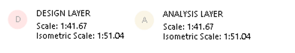
You can identify which layer you’re in by looking at the top right corner of the Graphic interface.
To change layers, right click anywhere on this interface, and select Switch layer, or use the keyboard shortcut Ctrl+Alt+D.
A summary of both layers and how to use them is listed below.
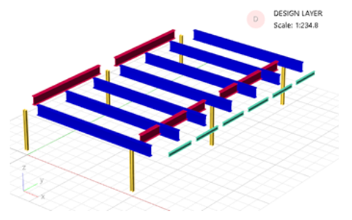
# Design layer
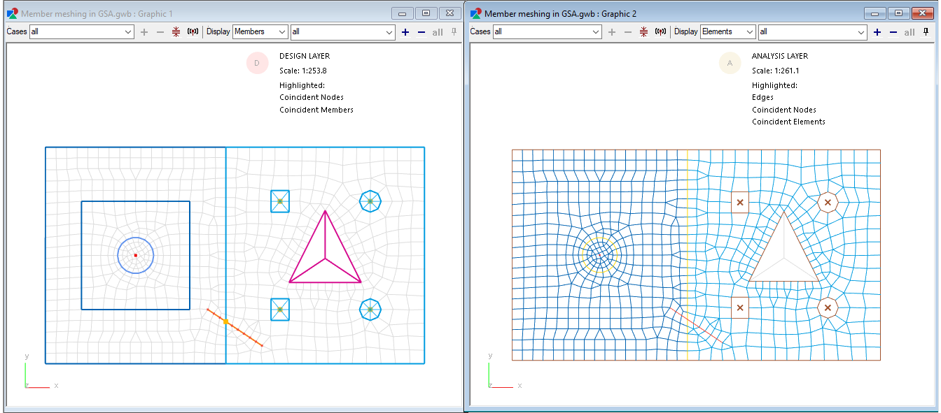
In the Design layer, entities are modelled as members. This layer represents how we might think about a component's physical structure, (i.e., an entire beam, an entire slab, etc).
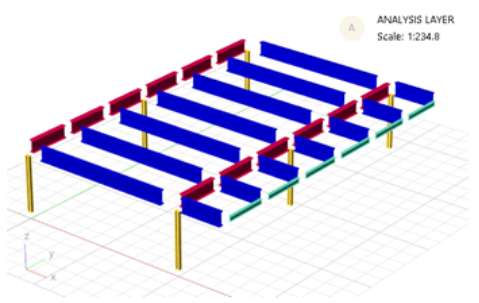
# Analysis layer
In the Analysis layer, entities are modelled as finite element analysis (FEA) elements. This layer represents the information that will be directly passed to the FEA solver, (i.e., a 1D beam element, a 1D compression only struct element, a 2D quad4 shell element, etc).
# Using layers in GSA
For most structures, it is recommended to start creating the geometry in the Design layer before creating the Analysis layer elements from the members. This allows for maximum flexibility and ensures that all intersections between any combination of 1D and 2D elements are noded out.
Any member properties (i.e., end releases, section properties, etc) will be passed onto the elements it creates.
# Applying changes to both layers
Changes are only applied to the layer that you are currently working on. To apply changes onto both layers, use one of the following coordination tools to sync the two layers:
Create elements from members - Creates analysis elements from the selected members.
Delete elements from members - Deletes analysis elements from the selected members.
Synchronise members and elements - If the geometry remains the same but properties between the two layers differ, this function can apply the member’s properties onto the constituent elements, or apply the elements' properties to the associated member.
Create members from elements - Creates members from analysis elements.
Note: As with initial geometry creation, it is recommended that changes be made in the Design layer to members which can then be synchronised to the elements.
# Functionality overview
The GSA development team is working on providing increased functionality to the design layer to allow the user the specify more attributes on a member level. At the time being, the following functionality is available in each layer:
| Function | Design layer (members) | Analysis layer (elements) |
|---|---|---|
| Create geometry | Yes, you can create members in the design layer | Yes, you can create elements in the analysis layer |
| Add load to 1D entities (nodes) | Yes | Yes |
| Add loads to 1D entities | No, but coming soon! | Yes, to 1D elements |
| Add loads to 2D entities | No, but coming soon! | Yes, to 2D elements |
| Add loads to 3D entities | No, but coming soon! | Yes, to 2D elements |
| Define restraints | Yes, only to nodes defined in design layer or part of member definition | Yes, to all nodes |
| Define constraints | Yes, only to nodes defined in design layer or part of member definition | Yes, to all nodes |
| Define 1D steel member design properties | Yes | No |
| Define 2D concrete design properties | Yes | No |