
# Thin Walled Sections
The effect of shear deformation on the results of a structural analysis
is usually negligible. Where it is more significant, it will usually
suffice to make a simple approximation to the shear deformation area of
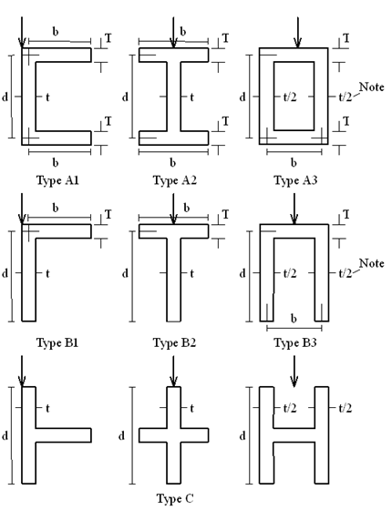
members with a cross-section such as those shown in Fig 1. The usual
approximation is, by analogy with a simple rectangular beam, to take
For those rare structures where the shear deformation is very important
it may be necessary to use a more exact value for the area. This Note
gives formulae for
These were derived from the virtual work formula, shear deflection per
unit length =
To see what the formulae mean in practice, they were applied to steel
sections taken from the handbook with the results shown in the table
below. In a web or flange with varying thickness,
It can be seen that, for sections with top and bottom flanges bending,
as nature intended, in their strong direction, the usual approximation
is satisfactory (although it should be noted that d is the distance
between flange centres, not overall depth). For the more bizarre
sections used in bending, values of
| Section | F |
|---|---|
| Bending in strong direction | |
| UB | 5.72 to 5.81 |
| Joist | 5.17 to 5.78 |
| UBP | 5.25 to 5.28 |
| UC | 5.28 to 5.53 |
| SHS | 5.0 |
| RHS | 5.0 to 5.49 |
| Channel | 5.06 to 5.60 |
| Angle | 3.68 to 4.62 |
| Tee from UB | 4.78 to 4.97 |
| Tee from UC | 4.11 to 4.35 |
| Cruciform | 5 |
| Bending in weak direction | |
| Channel | 2.12 to 3.78 |
| RHS | 4.02 to 5.0 |
| Angle | 2.55 to 3.68 (for |
| I’s, T’s, & cruciform | 5.0 |
With regard to calculating shear stresses, the exact distribution is not
normally required, or even usable, because Codes of Practice base the
shear strength on an allowable average shear stress calculated on the
total net area
is the shear flow in the web at the junction with the flange, and
is the maximum shear flow in the web, in which
For circular annuli, assuming that the stress is constant across the
wall thickness
# Formulae
Shear deformation area
Type A1
Types A2 & A3
Special case of A3 with constant wall thickness so that
Type B1
Special case of B1 with constant
Types B2 & B3
Special case of B3 with constant thickness
Type C
# Stress Factors
Type A1, A2 & A3
Type B1, B2 & B3