Constraint Axes
The constraint axis of a node (also referred to as the local axis of a node) is the axes that determines the directions of constraints (such as restraints, joints, rigid constraints, constraint equations) or local axis loads. Spring, mass and damper properties on a node also act in the constraint axis of the node.
The nodal constraint axes default to the Global axis, but you can set them to another axis set, whether Cartesian, cylindrical, or spherical. If the nodal axis is Cartesian then the local , , and will match the constraint axis directions, but for cylindrical and spherical constraint axes the local nodal axis directions depend on where the node is located in relation to the constrain axis origin.
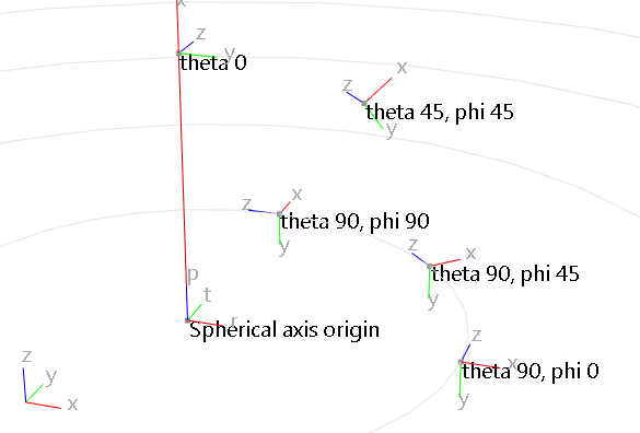
If the nodal constraint axis is cylindrical, a local Cartesian axis is calculated at the location of each node, with in the radial () direction, in the hoop () direction and unchanged. If the node is at the axis origin or on the axis axis (radius is zero) then the theta angle () is assumed to be zero, meaning that nodal constrained , , directions are the same as the cylindrical axis definition.
If the nodal constraint axis is spherical, a local Cartesian axis is calculated at the location of each node with in the radial direction, in the polar direction () and in the azimuthal direction (). If the node is at the axis origin (radius is zero) then the and φ angles are assumed to be zero and the nodal constrained , , directions are the same as the spherical axis definition. If the node is on the polar axis ( is non-zero, ) then the nodal constrained direction is set to be the same as the direction of the spherical axis definition.

If the node is positioned at any of these special cylindrical or spherical locations then it may be better to use a Cartesian constraint axis for those nodes to avoid unexpected results.
See Axis Sets for more information.