# Concrete 2D Member Design
# Introduction
Concrete 2D Member Design is a reinforcing option for slabs and walls that allows the design and rationalisation of reinforcement. It is a different approach to the existing RC slab contouring in that it gives a single bar size required over the whole member plus patches where extra reinforcement is required (ie at slab/column connections).
2D Member Design is a Design Task, which means that you set up and run the design calculation, then display the results.
# Video Tutorial
The following video describes how to set up and use the reinforced concrete member design module in GSA. Topics covered in this video include:
- Setting up global design parameters
- Setting up member properties
- Running the concrete member design module
- Displaying reinforcement
Oasys GSA - 10.1 RC Member Design from Oasys on Vimeo.
# Setting up the design
- Open Specification > Design and set the Concrete Design code
- Open Materials > Concrete and add a grade if necessary
- Open Materials > Reinforcement and add a grade if necessary
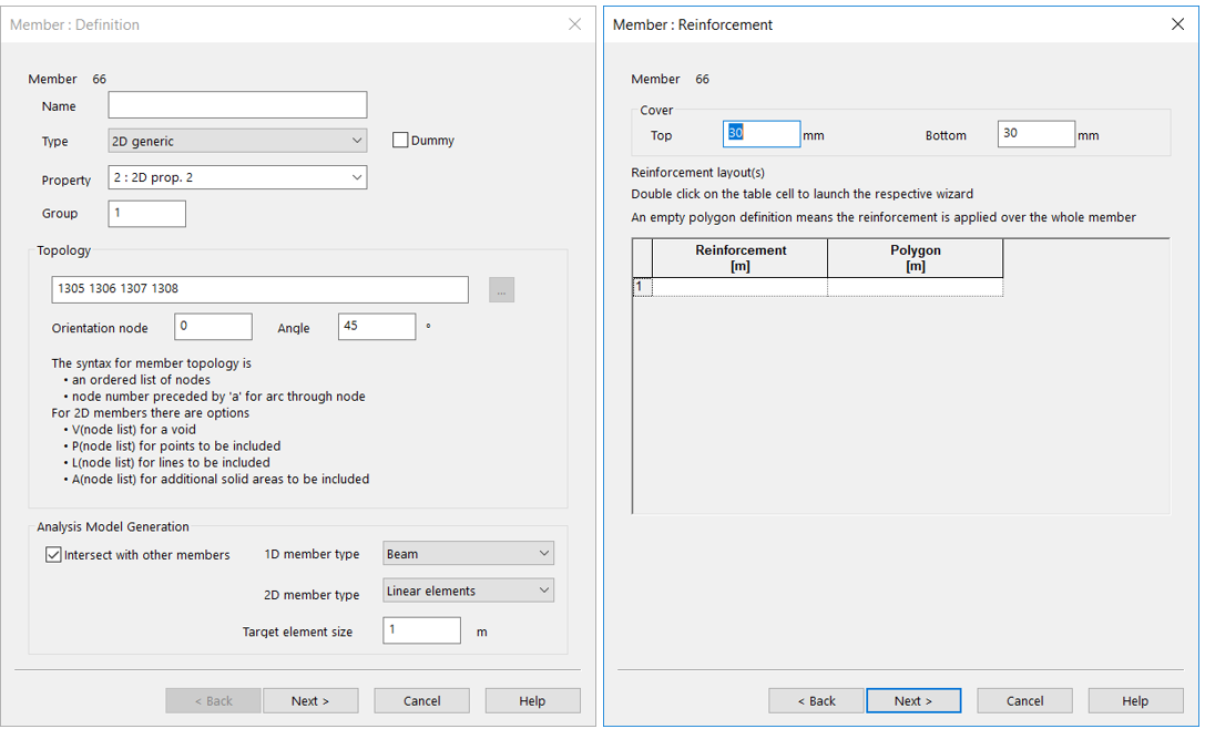
# Setting up the 2D Members
- Member: Definition - Ensure that the 2D Member orientation angle is set correctly for the required X direction reinforcement (properties pane or Member definition wizard
- Member: Reinforcement - Set the top and bottom cover
# Designing the reinforcement
- Analyse the model and create an ultimate limit state combination or envelope
- Add a new Design Task ( on the “GSA” toolbar or Design > New Design Task in the menu)
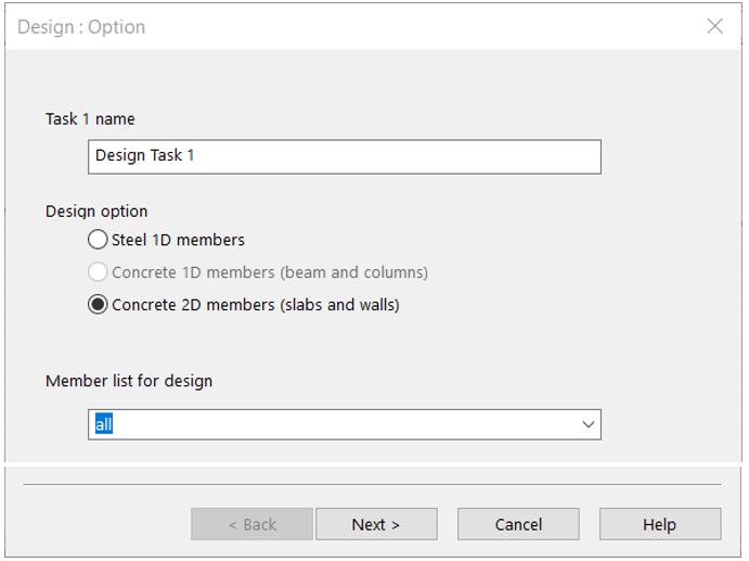
- Design: Option
- Name the task if required
- Set the design option to Concrete 2D Members
- Adjust the member list if required
# Design: Concrete 2D Member
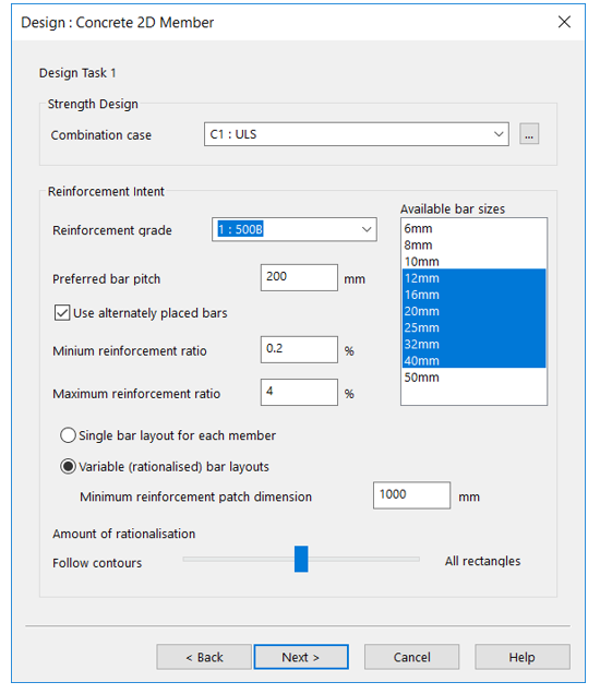
- Set the Strength Design > Combination case
- Choose the Reinforcement grade (if this is blank then you need to create a grade)
- Set the Preferred bar pitch (default 200 mm)
- Highlight the bars in the Available bar sizes list to use in the design
- Check
- Maximum and Minimum reinforcement ratios
- Single or Rationalised bar layout
- Minimum rebar patch size (for additional rebar over and above the default for the member)
- Adjust the Amount of Rationalisation slider on subsequent uses if the patch shapes were not as desired
- Design: Task Option
- Don’t Design Now saves and closes the dialog on Finish
- Design will create the reinforcement and log the results in the Member definitions
- Check will check that previously defined reinforcement is still acceptable for the new loading
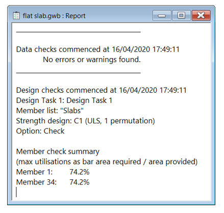
The report window will now show the high-level results.
# Displaying the reinforcement
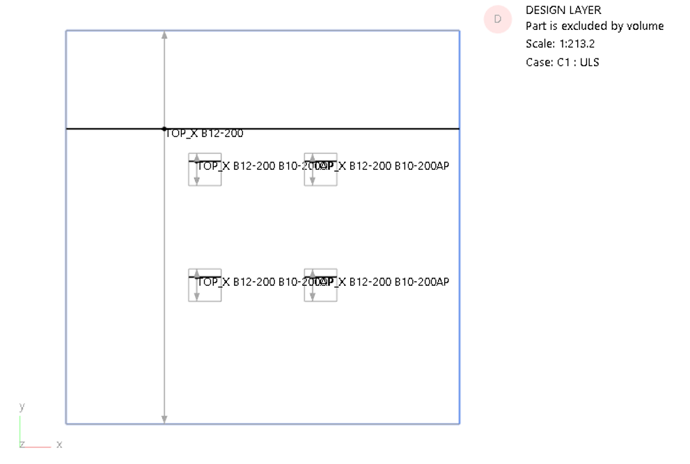
- Ensure that you are on the Design layer
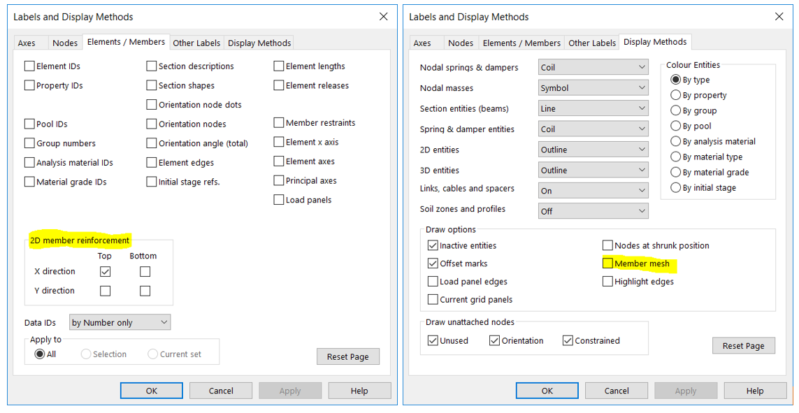
- Call up the Labels and Display Methods dialog ( or Graphic Settings > Labels)
- Elements / Members – check the 2D member reinforcement you wish to display
- Display methods – it can help to switch off the Member Mesh to make the reinforcement marks clearer)
# Editing the reinforcement
To edit and inspect the details of the reinforcement
- Select the 2D Member and run the Wizard
- The Reinforcement is recorded on the second page of the wizard The text callout is in the first column and the extent in the second
