# Loading
# Viewing Loads
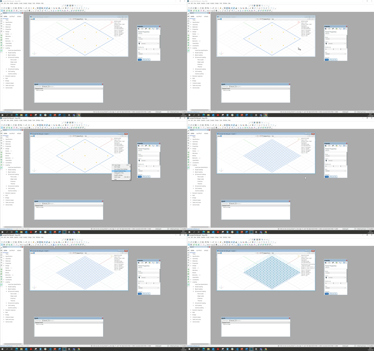
To view or set up loads you must be in the analysis layer.
- If you are in the design layer, right click the graphic display to change the layer.
- Click the loads icon to show your loads applied in the graphic view.
- Type "A" on the keyboard to graphically select which loads you want to annotate to display the loading value.
# Load Case Specification
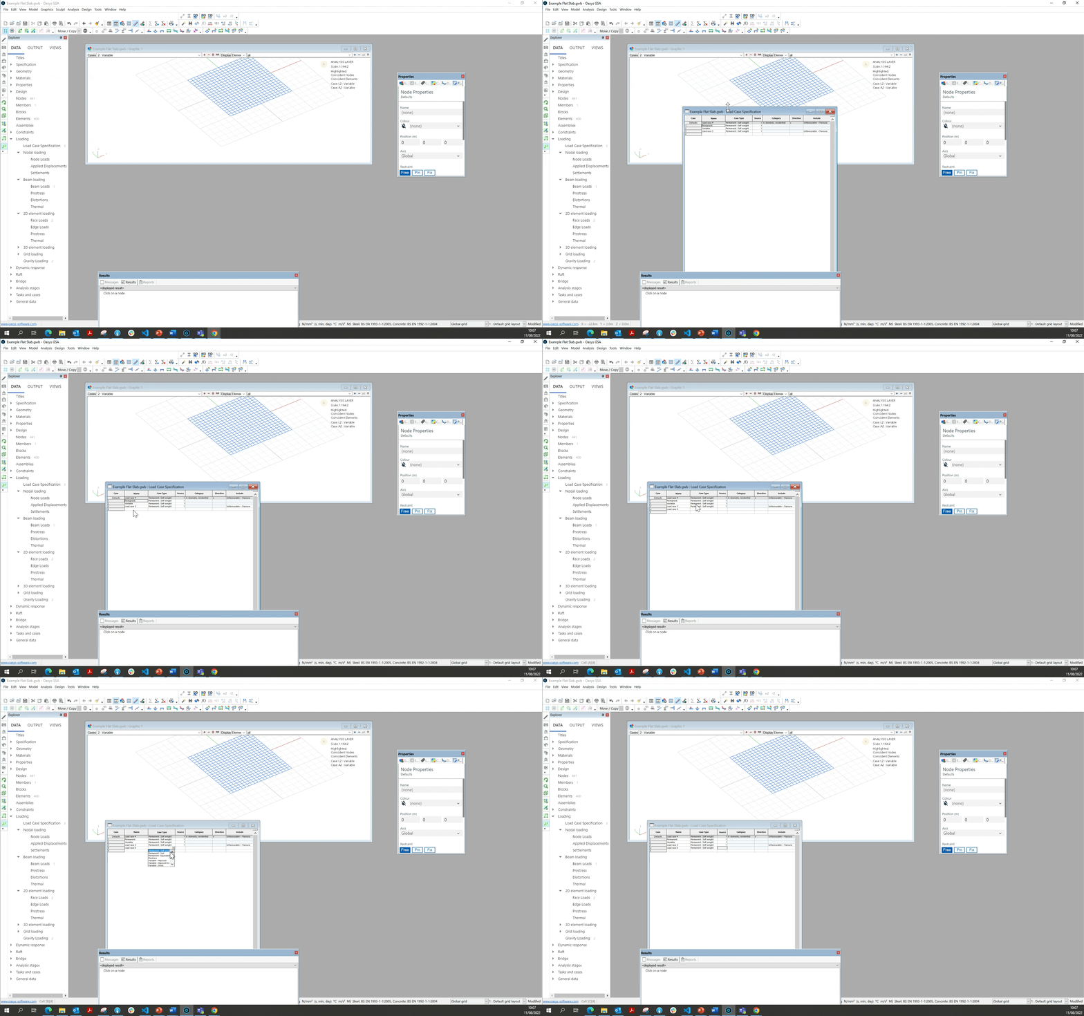
To define a load, you first need to specify your type of load case:
- Go to Explorer Pane > Data > Loading > Load case specification
- Name and categorise the load case by filling out the specifications in table.
# Nodal Loading
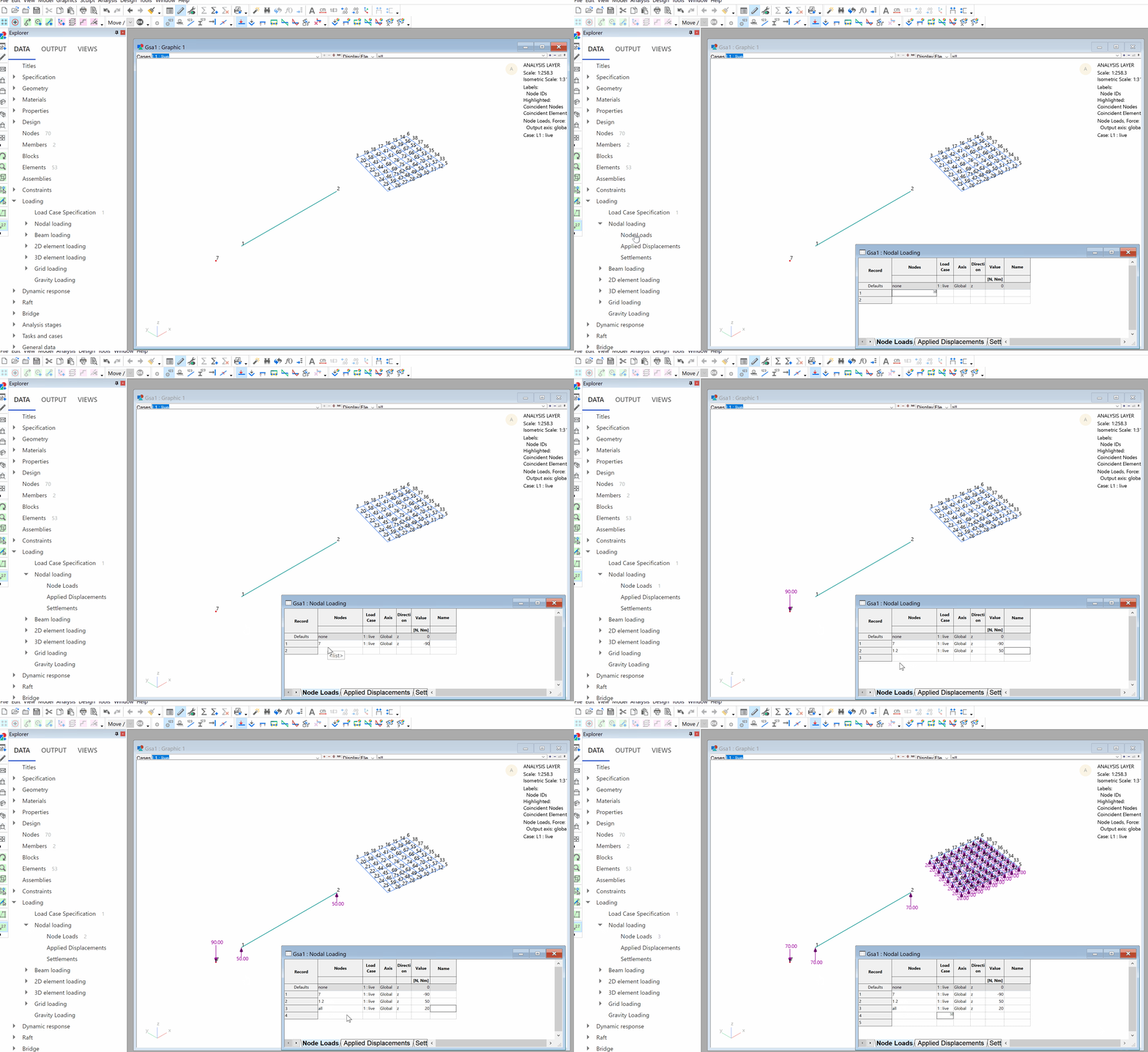
- Go to Explorer Pane > Data > Nodal loading
- Enter the nodes you want to apply the load to in the table.
Tip 1: You can use the keyboard shortcut n to select nodes on the graphic view, and then select ctrl+c to copy and ctrl+v paste the selected nodes into the nodal loading table.
Tip 2: You can also specify nodes by groups (e.g G1 for group 1) or lists (e.g. 'list name').
- Specify your load case, axis, direction and magnitude.
# Beam Loading
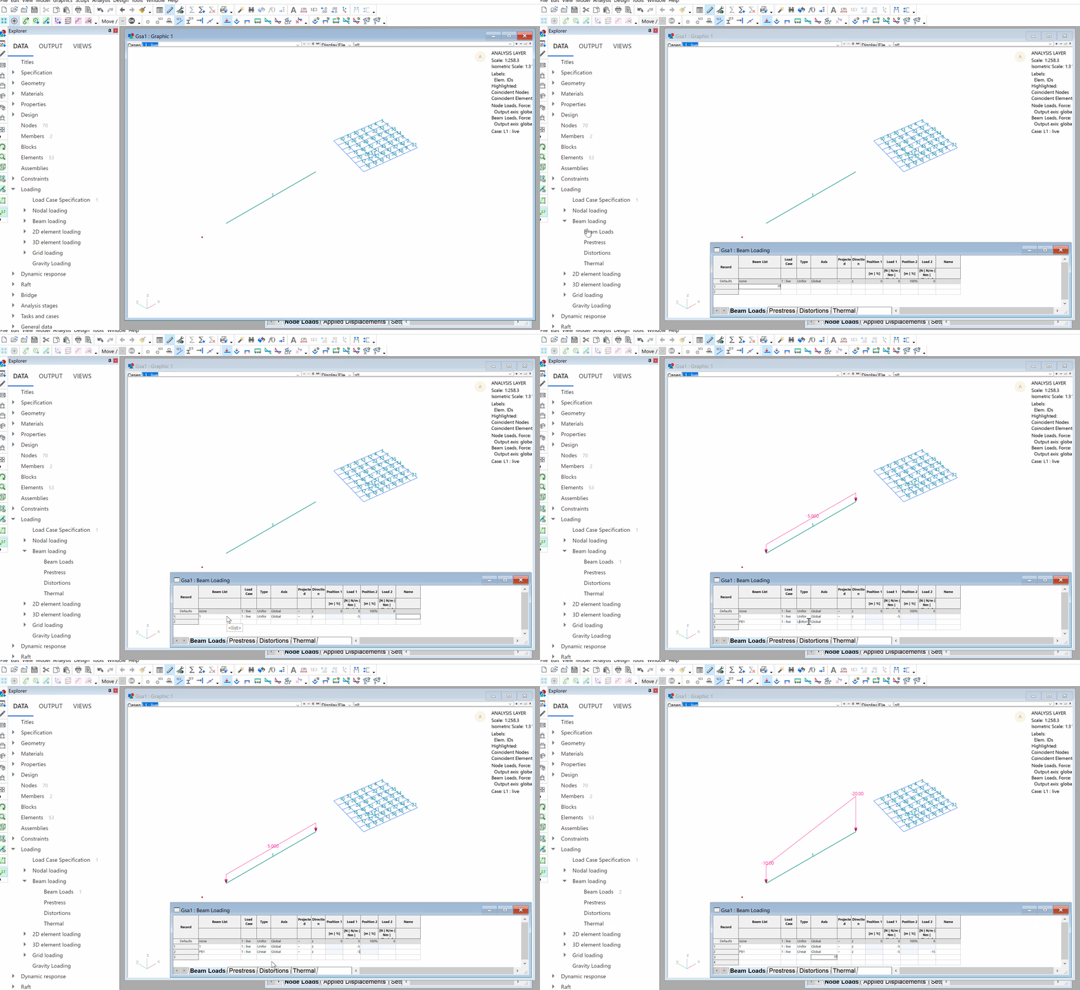
- Explorer Pane > Data > Beam loading > Beam Loads
- Enter the 1D elements you would like to apply the load to in the table.
Tip: You can load a group of elements by specifying its property, group or by list name. E.g., ‘PB1’, ‘G1’, 'list name'.
- Specify your load case, type, axis, direction and magnitude.
To apply prestress, distortions and thermal loading, follow a similar process using the the tables located under beam loading in the explorer pane.
# 2D Element Loading
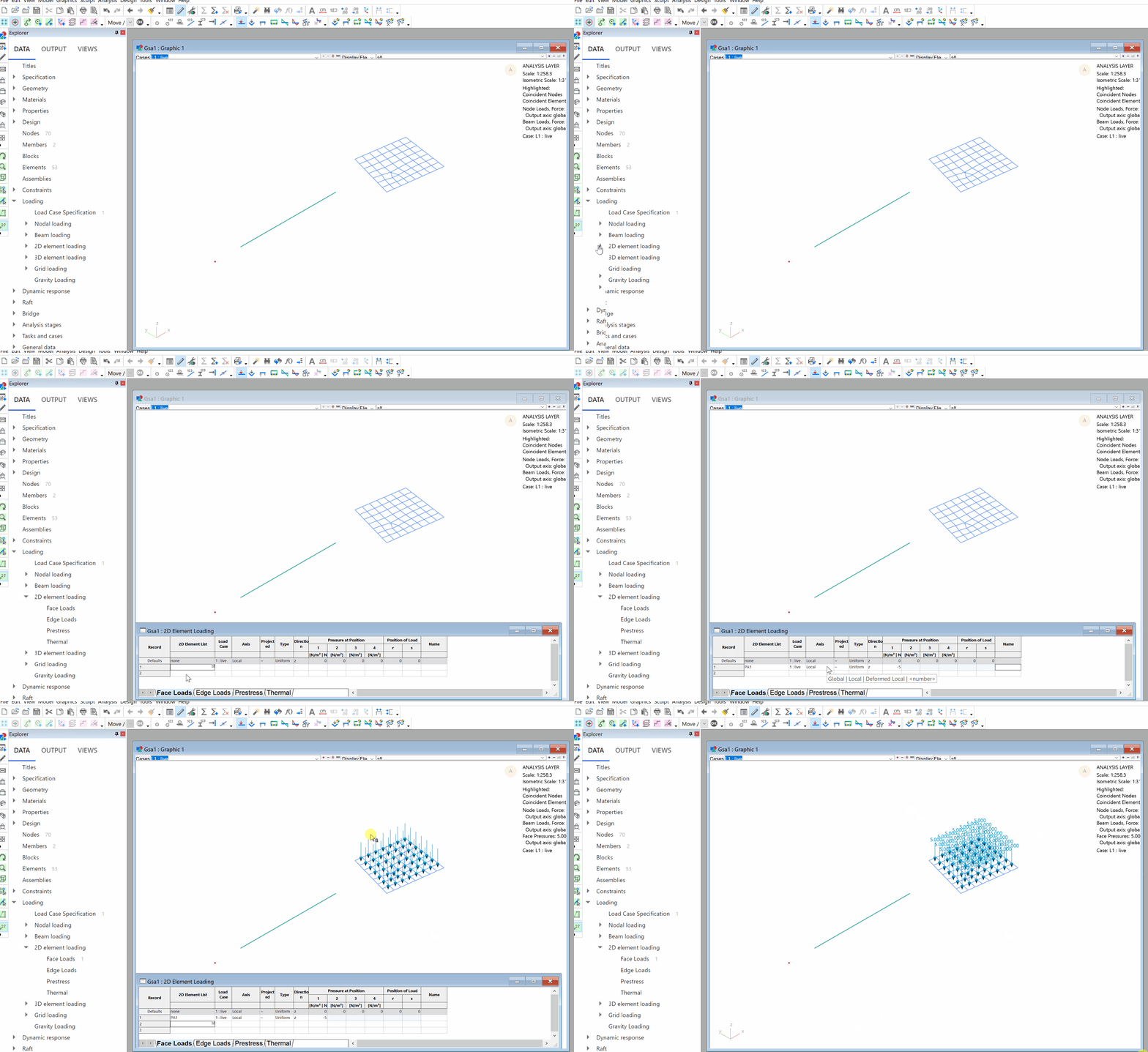
- Explorer Pane > Data > 2D element loading > Face Loads
- Double click the record number to bring up the face load wizard or modify the table directly to input load case, type, axis, direction and magnitude.
Note You have the option to choose from uniform, variable, or point for type of loading.
To apply edge, prestress, and thermal loading, follow a similar process using the the tables located under face loads loading in the explorer pane.
# Gravity Loading
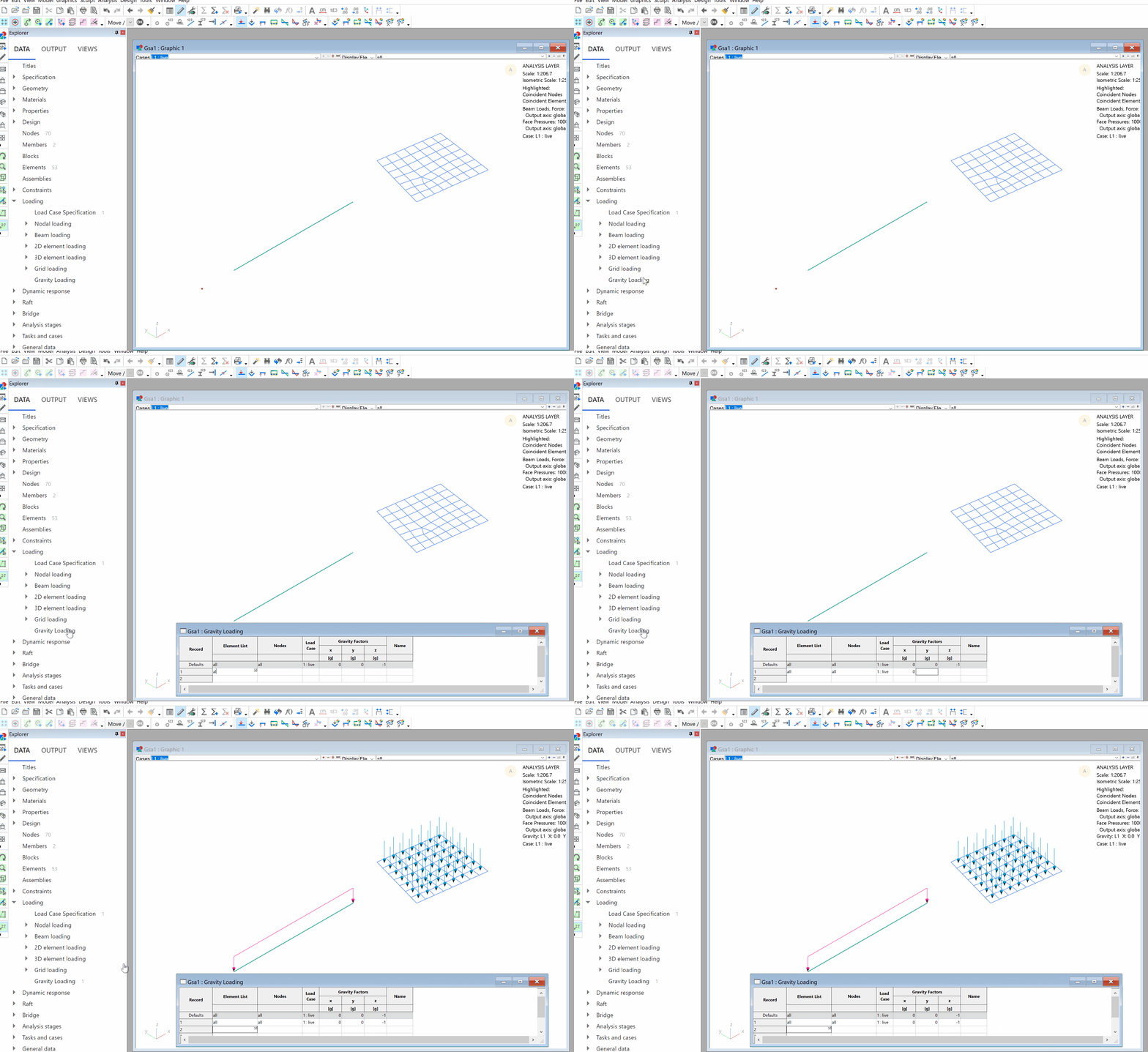
- Explorer Pane > Data > Gravity Loading
- Enter which elements and nodes you would like to apply an acceleration to in the table.
# Grid Area Loads
The following video shows how to add grid area loads to a surface and how to expand the load for checking purposes.
Oasys GSA - creating grid planes, surfaces, and area loads from Oasys on Vimeo.
See grid loads theory for more information on how grid loads are calculated.
