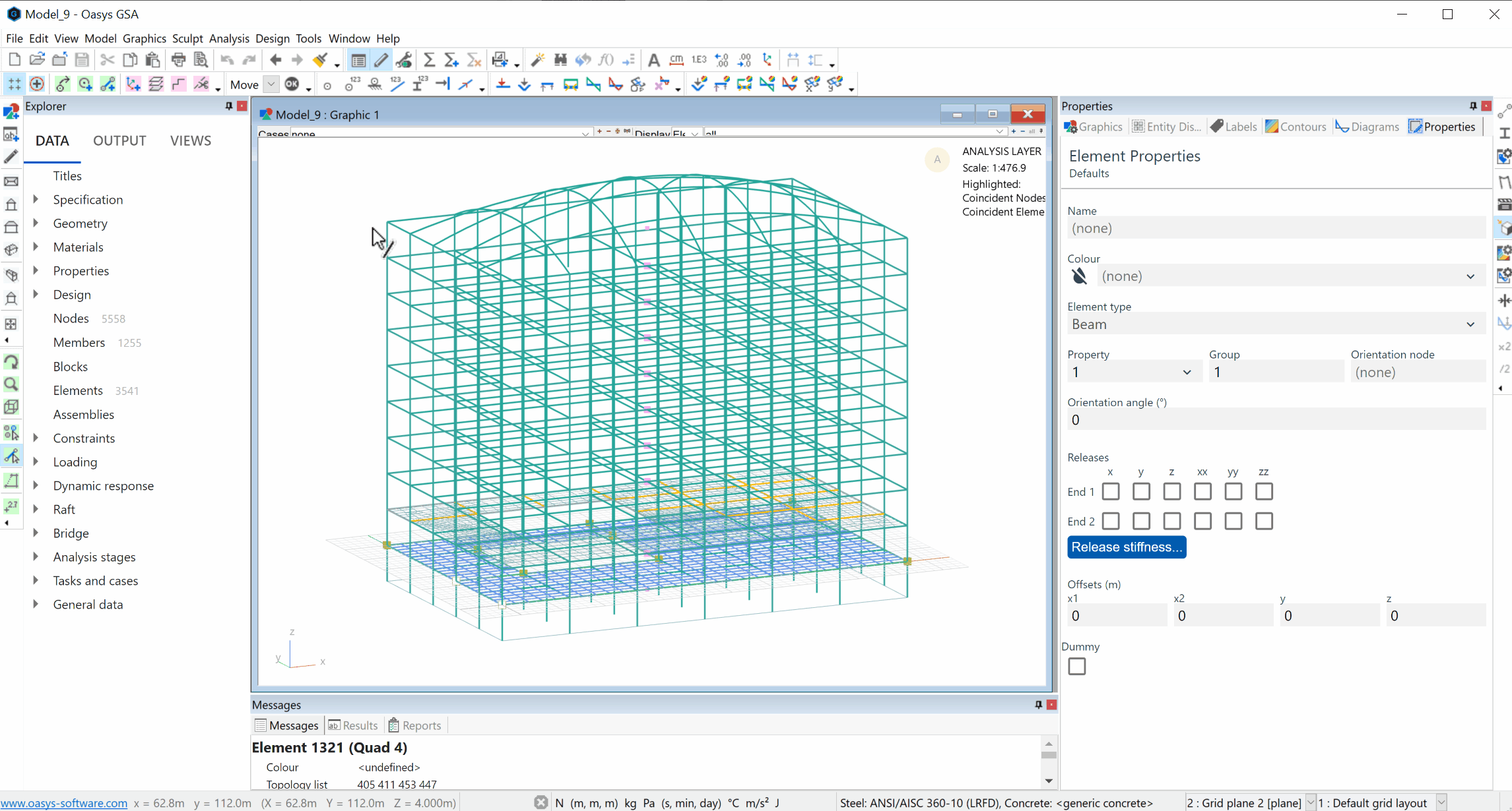
# Visualising model properties
# Key icons
| Tool | Description |
|---|---|
 | Labels |
 | Labels and display methods |
 | Label element IDs |
 | Label element releases |
 | Label node IDs |
 | Label restraints |
# Label node IDs
To visualise node numbers within the model, click the Label node IDs button in the top GSA toolbar, shown here above the graphics window.
# Label element IDs
To visualise element numbers within the model, click the Label element IDs button in the top GSA toolbar.
# Label restraints
To visualise restraints within the model, click the Label restraints button in the top GSA toolbar.
# Extruded members
To visualise extruded members within the model, click the Labels tab in the right hand properties panel, then tick Section display.

# Section descriptions
To see section descriptions within the model, go to the properties panel and select Labels > On elements and members > Section descriptions and check the adjacent box.
# Label element releases
To view element releases within the model, click the Label element releases button in the GSA toolbar above the graphics window.
# Visualise local axes
To visualise all local element axes, go to the properties panel and select Labels > On elements and members > Element axes and check the adjacent box.
# Display customisation
For further customisation of display methods, go to the properties panel, select Labels and click the Labels and display methods button
In this window, under the Display methods tab, the current display settings for various elements and visual effects can be modified.
# Sophisticated graphic selection tools
# String
Use the Select elements tool  to enter the select elements cursor mode.
This will select a string of elements attached to and aligned with any currently selected elements.
The Select nodes tool  will take you to the select nodes cursor mode, where nodes along the string of elements are selected.
Use the Polyline tool  to go to the polyline cursor mode.
The polyline is extended forward from the last polyline segment. This adds vertices at the positions of the closest aligned nodes or grid points displayed. The straightness tolerance preference determines whether an element, node or grid point is aligned, allowing this command to be used to select curved strings.
# Highest coincident
In the select nodes or select elements cursor modes this deselects all but the highest numbered coincident items in the current selection.
Click the Select nodes
or Select elements / members tool Click and drag to make your selection on the graphic display.
In the top menu go to Edit > Select highest coincident.
Example: If nodes 1 to 30 are selected and nodes 1, 2, 11 and 12 are coincident then this command will only select nodes 11 and 22.
Note: This command is useful for deleting coincident nodes and elements. Nodes may not be deleted graphically when they are referred to by elements.
# Close to vertical 1D elements
In the select elements cursor mode, this selects all 1D elements that are within 1 degree of vertical, i.e., not defined as vertical by the local element axes definition.
Click on the Select elements / members tool
Select elements on the graphic display.
In the top menu go to Edit > Select close to vertical 1D elements
# Select by criteria
This command allows you to select a set of entities based on the criteria that you are defining. This criteria can be defined by coordinates, colours or by list.
In the top menu go to Edit > Select by criteria
In the Select by criteria dialogue box, click Add to tick entities you wish to include.
Note: Rules are displayed in the dialogue box. Use the drop down menu to choose which specified entities are visible on the graphic display.