# Creating 3D members
This section describes how to create 3D members in GSA.
3D members can be created in the Design layer by defining their faces with a series of triangles. Corner nodes are referenced in an order that divides the member's face into triangles.
The topology of a member can be defined in the Members table, by drawing connections between nodes using the Sculpt tools. The following sections provide an example using these two methods with various shapes.
# Setting the example
# Square
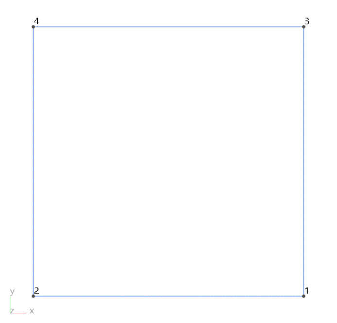
The surface of a square can be define as [123;234] or by repeating the nodes [1234] so that each trio of node numbers defines a triangular face.
# Triangle
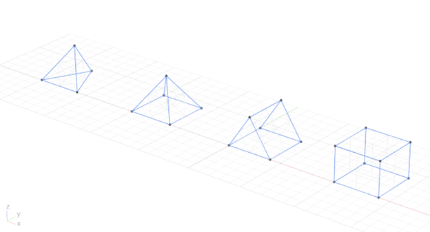
While each triangle is flat by definition, the triangle strips do not need to be. Continuing with our example, the above tetrahedron can be defined with the node sequence: [123412], mixing and matching these individual faces and triangle strips as required.

# Cube
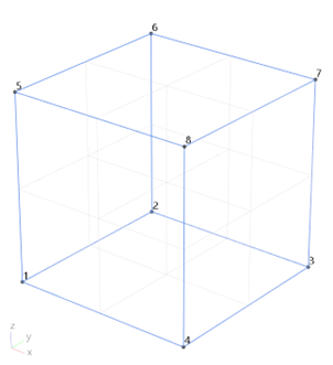
A cube can be defined with the node sequences for the bottom face, the top face, and then the sides: [1243;5687;1548372615].
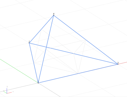
# Tetrahedron
The topology of the tetrahedron member (below) can be defined by specifying the corner nodes on each face, separated by a semicolon: [123;234;341;412] in the Members table or by using the Sculpt tools to draw connections between nodes in the same sequences to define the triangular faces within the tetrahedron.
Tip: 3D members are defined by a closed boundary mesh of triangles and/or triangle strips (opens new window). See also Member definition > 3D members in this GSA documentation site (opens new window).
# Draw a 3D member using Sculpt tools
Note: If you have already added any necessary nodes into the model, skip steps 1 and 2 below.
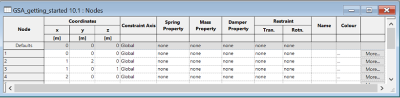
Go to: Explorer pane> Data > Nodes to open the Nodes data table.
Click the first cell, enter your own values and/or press Enter to copy default values into any empty fields. The values from our example can be used to get you started.
| Row | x | y | z | Action |
|---|---|---|---|---|
| Row 1 | 0 | 0 | 0 | Click in the first cell, press Enter to apply default values only. |
| Row 2 | 1 | 2 | 0 | press Enter to apply defaults to other columns |
| Row 3 | 1 | 0 | 1 | press Enter |
| Row 4 | 2 | 0 | 0 | press Enter |
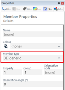
From the Design layer, select the Add entities tool:
 or use keyboard shortcut Ctrl+Shift+Alt+E.
In the Properties pane, set the member type to 3D generic.
Tip: Select Isometric view:
from the Views toolbar (opens new window) or keyboard shortcut I to interact with the nodes in 3D.
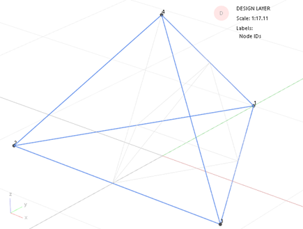
Select the Label node IDs icon:
 from the toolbar to display the node IDs.
Connect the nodes in the order of 123412 so that the faces of the tetrahedron member do not repeat. Following the example from above, each trio of node numbers in sequence defines a triangular face such as the following: [123;234;341;412].
# Creating 3D members in the Members table
To create the above tetrahedron, open the Members table from the Data explorer.
In a blank row:
Set type to 3D generic
Set Property to the required value (defined in the Data explorer table Properties > 3D Properties).
Set the Group to the required value or accept the default value by clicking into the next cell.
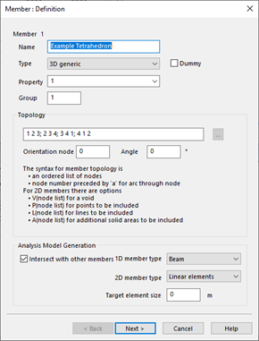
In the Topology field, using our example values, type: [123;234;341;412].
Define the values in the other columns or press Enter to accept the default values.
The table should now look something like the example below.
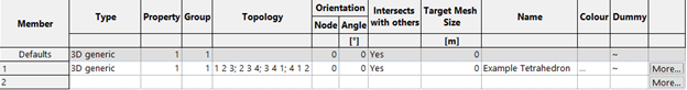
Tip: Clicking on More or double click on the rwo to open the member definition dialog.