1D element axes
Beam axes
Symmetry about the axis
In most cases beams have symmetry about one axis or both axes (e.g., a rectangular, circular, I-beam or tee section). In these cases the principal axes of the beam correspond with the local axes. This means that the bending behaviour is governed by: and and the term is zero.
No symmetry about the axis
When a section lacks symmetry about both axes, the cross term is no longer zero. This means that a load in the y direction will produce a displacement in y and z directions.
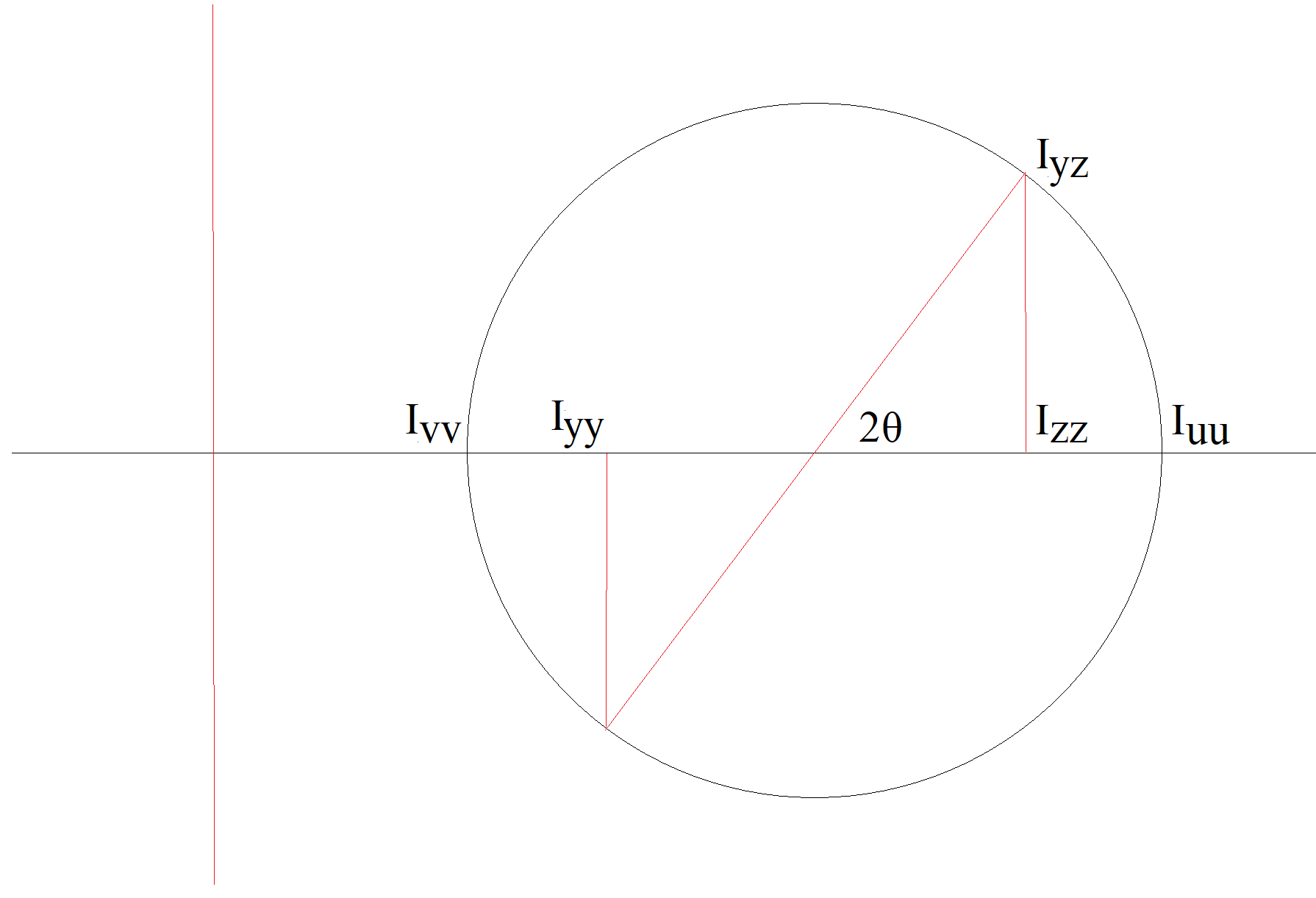
The angle of the principal second moments of area can be calculated from:
The second moments of area in the u and v axes are:
These relationships can be visualised using a Mohr's circle approach similar to stress.
Note: GSA gives the option to use either principal second moments of area, or local second moments of area (ignoring the term). Principal moments most often apply to asymmetric or angle sections; by using this option it is possible to capture sideways deflection. Therefore, the latter option is not recommended.
Section, spring, and damper elements
Section elements include beams, bars, rods, ties, and struts are defined by two nodes locating the ends of the element. The x axis of the element is along the axis of the element (taking account of any offsets) from the first topology item to the second.
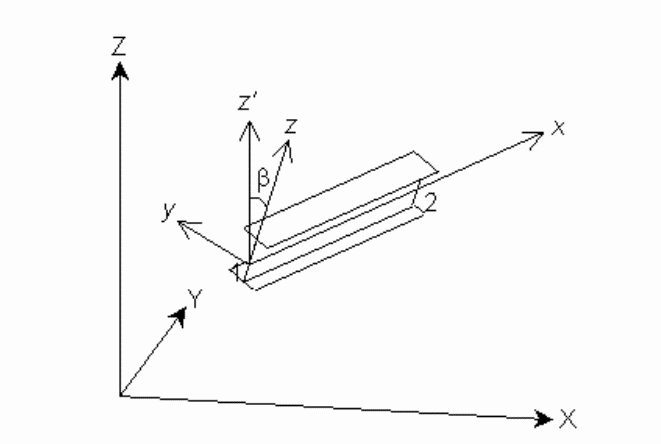
The definition of the element y and z axes then depends on the element’s orientation, verticality, orientation node (for section elements) and orientation angle. The element is considered vertical in GSA if the element is within the ‘vertical element tolerance’.
Non-vertical elements
If an orientation node is not specified, the element z axis of a non-vertical element defaults to lying in the vertical plane through the element and is directed in the positive sense of the global Z direction. The element y axis is orthogonal to the element z and x axes. The element y and z axes may be rotated out of this default position by the orientation angle.

Vertical elements
If an orientation node is not specified, the element y axis of a vertical element defaults to being parallel to and is directed in the positive sense of the global Y axis. The element z axis is orthogonal to the element x and y axes. The element y and z axes may be rotated out of this default position by the orientation angle.
Orientation node
For a section element (but not springs or dampers) an orientation node can be specified. If an orientation node is specified, the element x-y plane is defined by the element x axis and a vector from the first topology position to the orientation node, such that the node has a positive y coordinate. The element z axis is orthogonal to the element x and y axes. Specifying an orientation node overrides the “vertical element” and “non-vertical element” definitions described above. The element y and z axes may be rotated out of this default position by the orientation angle.
Orientation angle
The element y and z axes are rotated from their default positions about the element x axis by the orientation angle in the direction following the right hand screw rule. This occurs regardless of whether or not the element is vertical and of whether or not an orientation node is specified.
Cable elements
Cable elements act only in the axial direction, so only the x axis is defined following the same definition as the x axis of a beam element.
Link elements
The local axes of link elements are the same as those of the primary node.