RC Slab Analysis Procedure
The following summarizes the procedure followed by RCSlab:
- Adjust, where necessary, the applied moments for minimum eccentricities.
- Split the section into three layers with the central layer unstressed and the outer layers taking in-plane stresses, the thicknesses corresponding to an acceptable neutral axis depth; calculate the stresses applied to each layer.
- Calculate the stress to be taken by the concrete in each layer and the stress from each layer to be taken by reinforcement.
- Calculate the force to be taken by each of the four sets of reinforcement (two faces, two directions) taking into account their positions relative to the layers.
- Determine section strains compatible with the neutral axis depths implied by the layer thicknesses in 5.0.2 and the concrete strains in the outer layers from 5.0.3 for top and bottom layers.
- Determine reinforcement strains compatible with the section strains.
- From the strains, calculate the stress in each of the four sets of reinforcement.
- Knowing the force to be taken by each of the four sets of reinforcement and the stress in each set of reinforcement, calculate the reinforcement areas required; these should not be less than the specified minimum values.
- Repeat as necessary from 5.0.2, adjusting the layer thicknesses to achieve the minimum total area of reinforcement.
- Where in-plane effects dominate, repeat from 5.0.2 adopting a model with the central layer stressed.
- The design reinforcement areas correspond to the layer arrangement giving the minimum total area of reinforcement.
- To speed up the calculation, an option is available to adopt a non-iterative technique where the loading is primarily either in-plane or out-of-plane.
Inclusion of moments resulting from additional and minimum eccentricities
The applied moments are adjusted to take into account the additional and minimum eccentricities of applied axial forces. The additional eccentricity, which can be used to model tolerances and second-order effects, is determined by the user; applied bending moments are increased by compressive principal axial forces but are not adjusted for tensile principal axial forces. The components of in-plane force in the orthogonal directions for use with the additional eccentricity, , and , are calculated assuming the angle between the principal direction and the x-axis is unchanged.
The default value of the minimum eccentricity, which can be overwritten, is taken from the chosen design code; this value, and all other code-dependent values, are given in Appendix 3. If the absolute value of the applied moment exceeds the sum of the additional and minimum eccentricity moments for , and , then the applied moments are increased in magnitude by their respective additional moments. Otherwise two sets of applied moments are calculated, corresponding to eccentricities applied in the two senses.
where takes the value of -1 for the first set and +1 for the second set.
For example, if the applied, additional, and minimum eccentricity
moments were 75 kNm, 50 kNm and 60 kNm respectively, the design moments
for the two sets would be
75 – 50 - 60 = -35 kNm and 75 + 50 = 125 kNm respectively. It should be
noted that no specific allowance is made for slenderness.
Division of section into layers
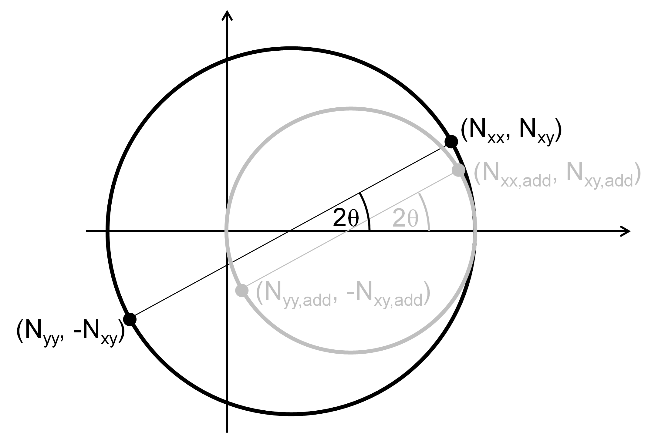
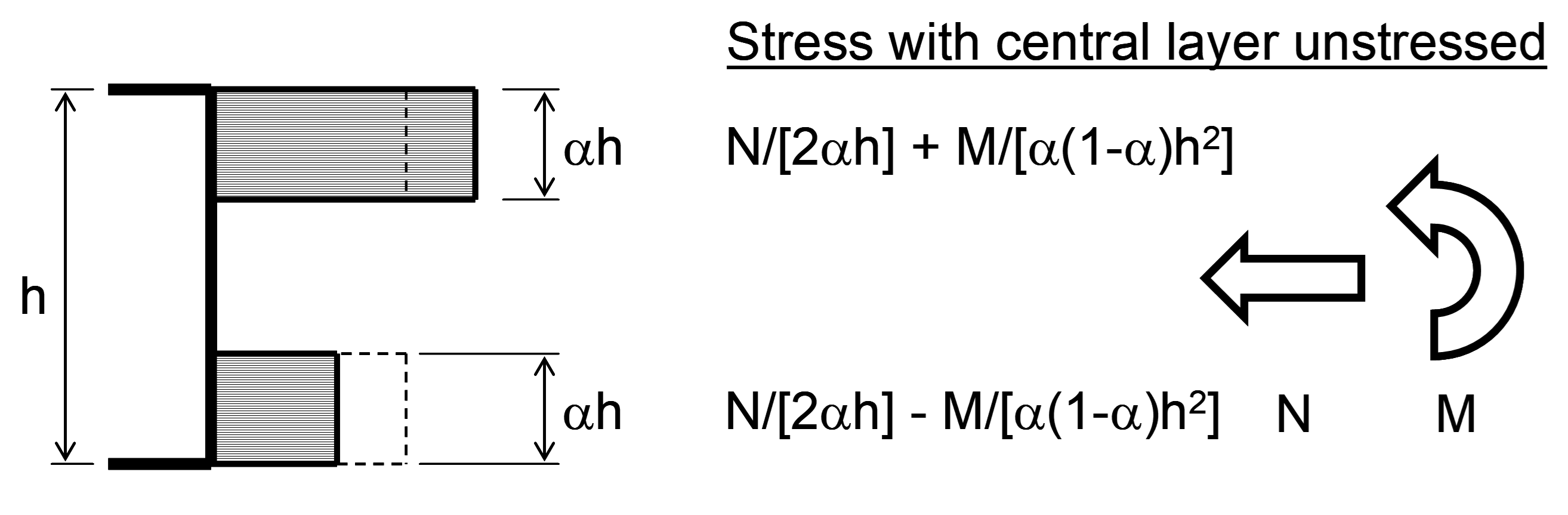
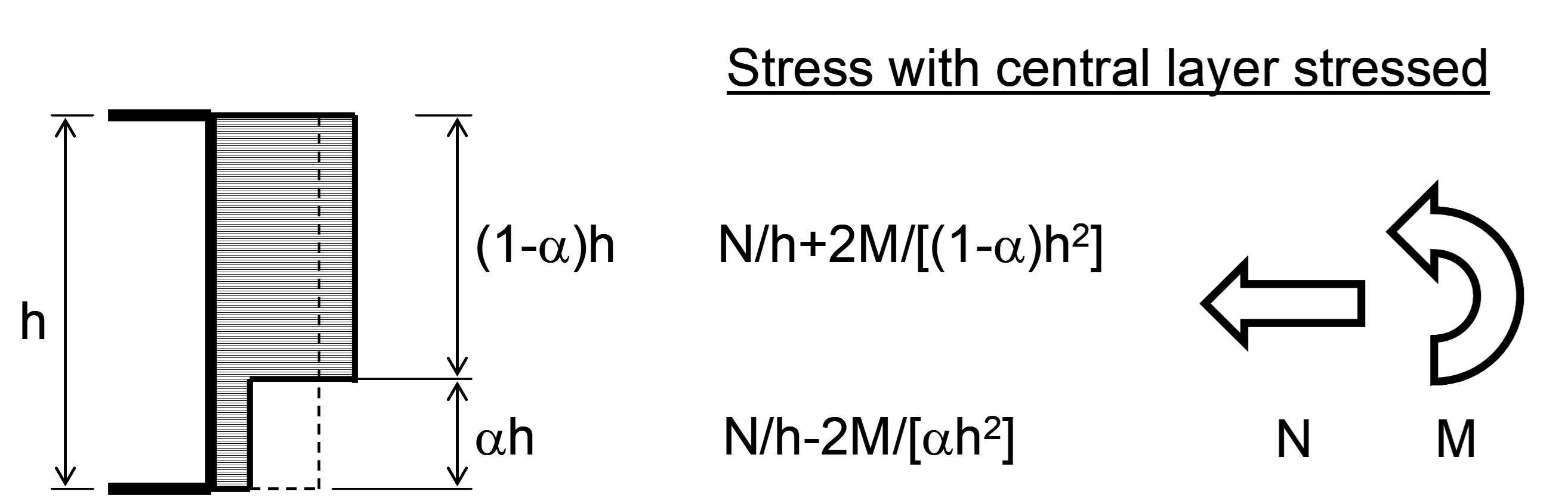
The section is divided into three layers, each with constant in-plane stress. The outer layers both have a thickness of , where is the proportion of the total section thickness, ; the inner layer is therefore of thickness . In-plane forces are resisted either by the outer layers alone or, if there is sufficient in-plane compression, by all three layers. The outer layers also resist the moments resulting from out-of-plane forces.
(In this figure, represents , or and represents , or respectively.)
The program determines iteratively the value of α that gives the lowest total area of reinforcement, . Calculations are first performed for the condition with the central layer unstressed, and then repeated for the condition with it stressed, although the latter results are only valid if there is no tension reinforcement, or if tension reinforcement is required in both faces, in a particular direction.
The minimum valid value for α is zero; any code-specified maximum lever arm is converted into an equivalent maximum strain in the reinforcement, which is explicitly checked. Where the central layer is unstressed, and the axial compression in the reinforcement direction with the larger force eccentricity is less than , the maximum valid value is given by
where the axial compression in this direction exceeds , ; for intermediate values of axial compression, the value of is linearly interpolated between these two extremes. Where all three layers are stressed, the maximum valid value for α is given by .
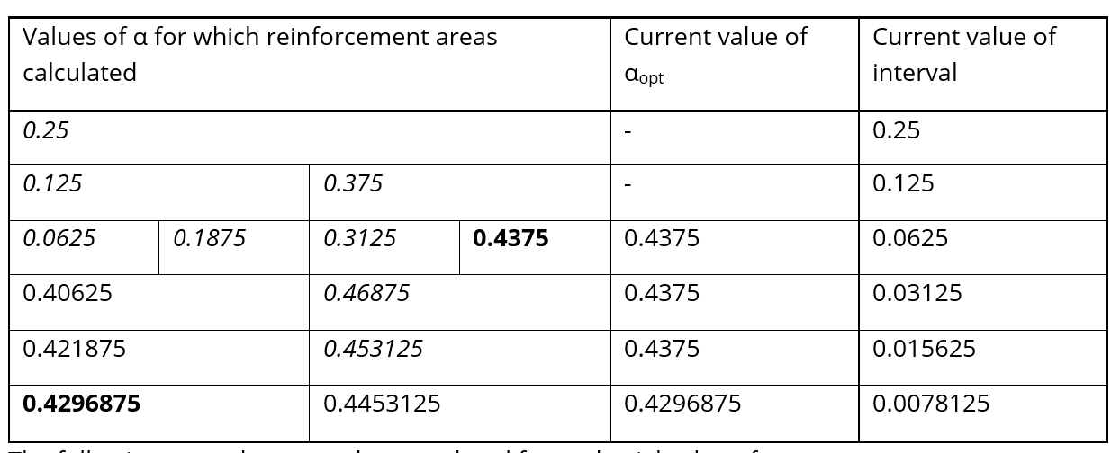
The initial value of is taken as . If this value does not give a valid result, calculations are performed for and . If neither of these values results in a valid result, the additional four values at the eighth points of the range are calculated. This process is repeated, using sixteenth points etc, until there is at least one valid result or the interval between adjacent values of α falls below a limiting value of 0.02.
Once a valid value of α has been determined, only the values lying between this value and the previously calculated values of on either side are considered, halving the interval. This is repeated, halving the interval for each turn, until it falls below a limiting value of 0.005.
In the following example, it has been assumed that , , valid results are obtained for , , and, for simplicity, the area of reinforcement increases linearly with the difference between and . The optimisation process stops when the interval is less than 0.005. The program would calculate areas of reinforcement for the following values of . Values of in italics indicate no valid solution; values in bold indicate this is a revised optimum value.
The following procedure must be completed for each trial value of .
Calculation of stress to be taken by reinforcement in a layer
The design strength of the concrete, , depends on the extent of cracking and needs not be the same in different layers. For each layer, the principal applied stresses, and with being more tensile, are calculated from the orthogonal stresses. If is compressive, the uncracked concrete strength, , is used. Otherwise the design strength depends on the ratio of to the tensile strength of the concrete, ; the strength is calculated as , but not less than the cracked concrete strength, . The concrete strengths are code dependent.
If is not tensile and is not greater than , then reinforcement is not required to take any stress from this layer. Otherwise, the reinforcement must take sufficient stress to achieve equilibrium without either overstressing the concrete or requiring it to take tension. The general expressions are given in Appendix 1.
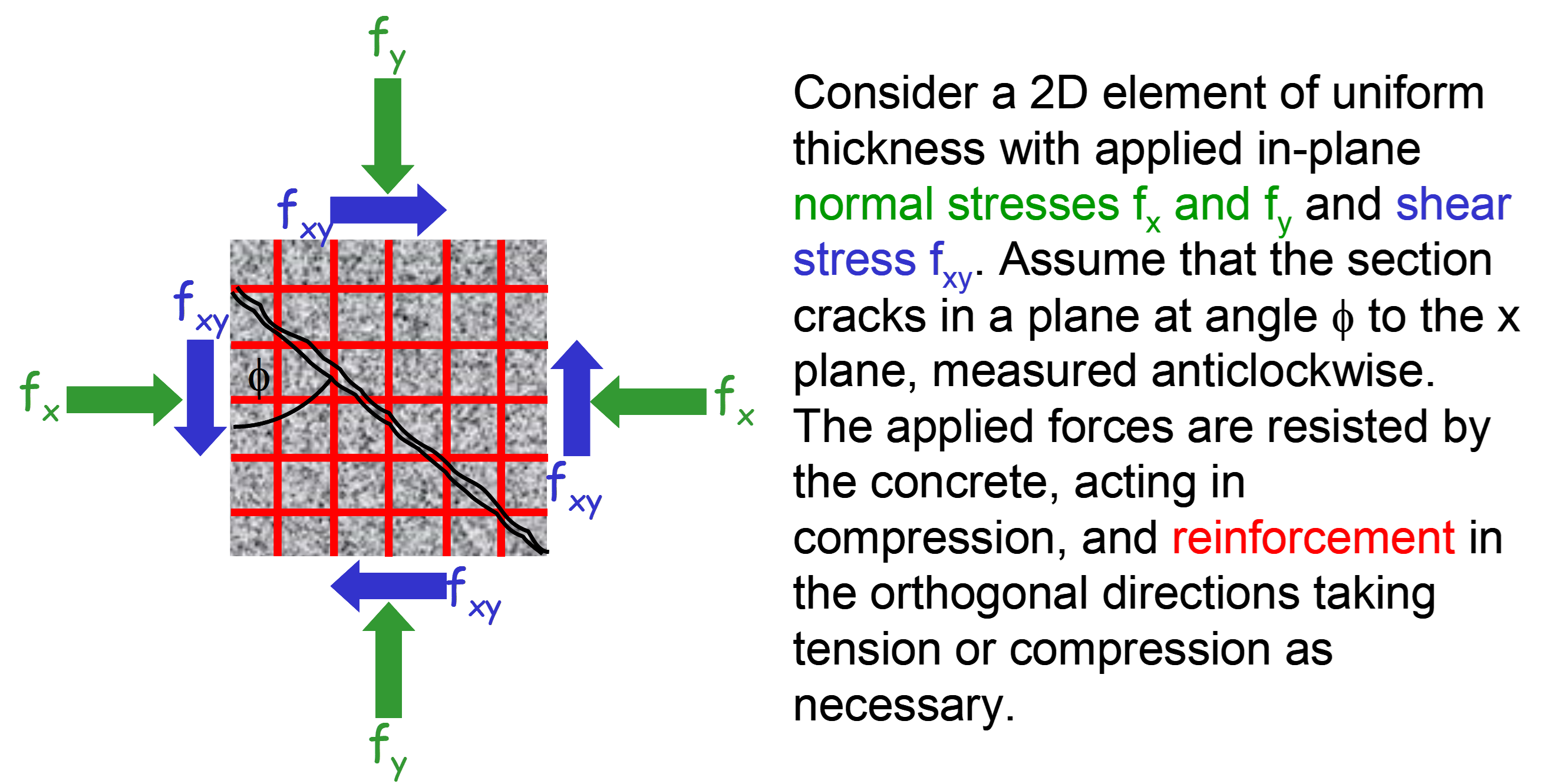
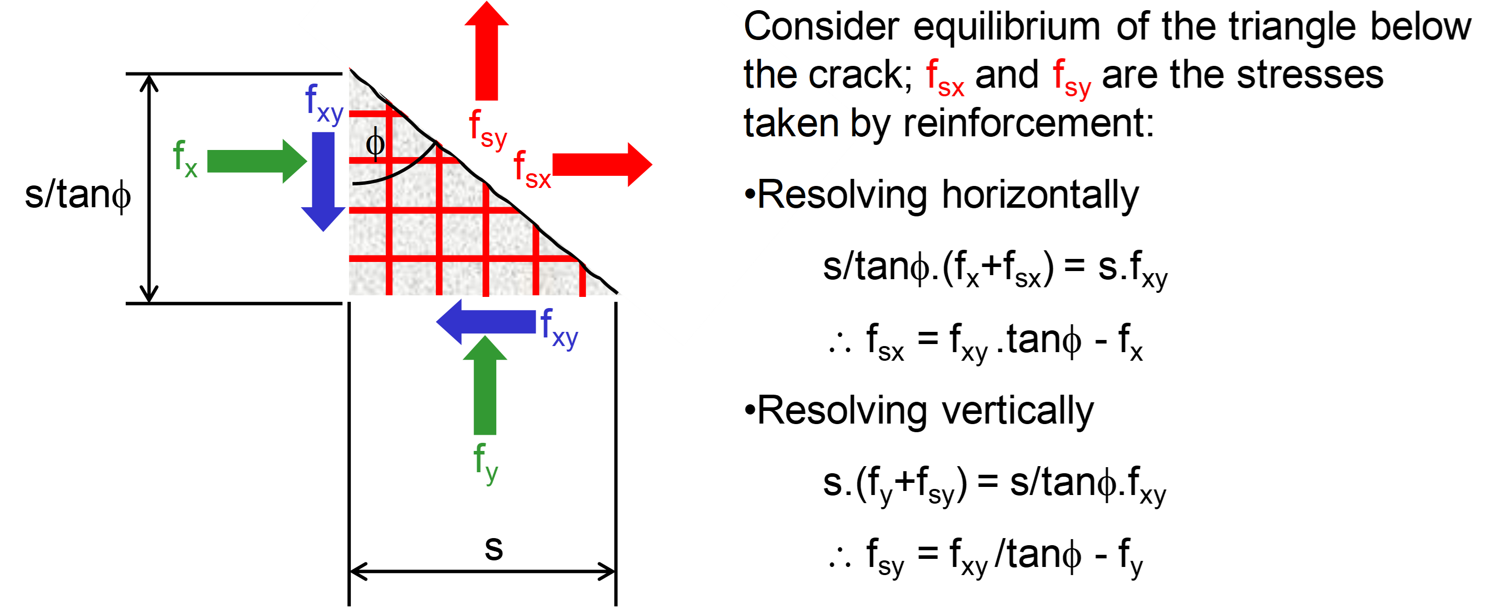
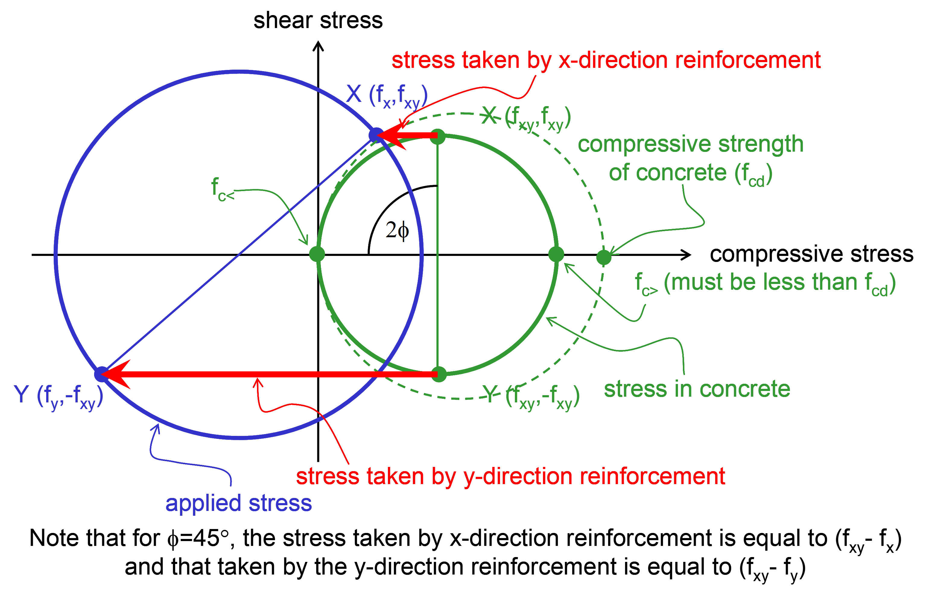
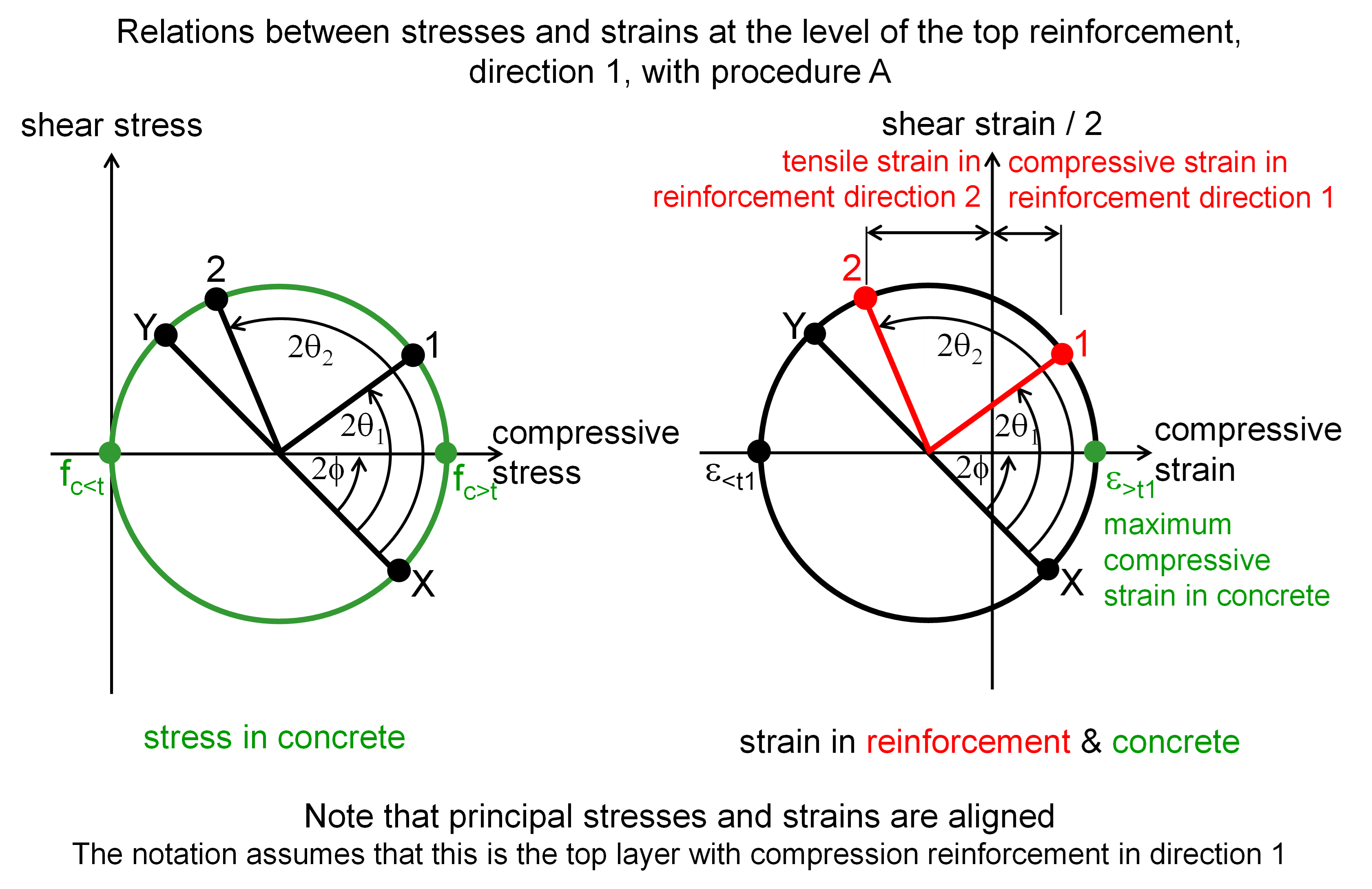
The following diagrams illustrate the situation within a layer where the reinforcement is aligned with the x and y directions.
The angle at which the cracks form under the design loads, , is not generally equal to the angle of the initial cracks, which depends on the direction of principal tensile stress. As reinforcement yields, the angle of cracking rotates, and this angle may be limited by a design code or the user. RCSlab selects the angle, complying with any limitation, which results in the lowest total area of reinforcement. This often corresponds to the angle that also gives rise to the minimum stress in the concrete.
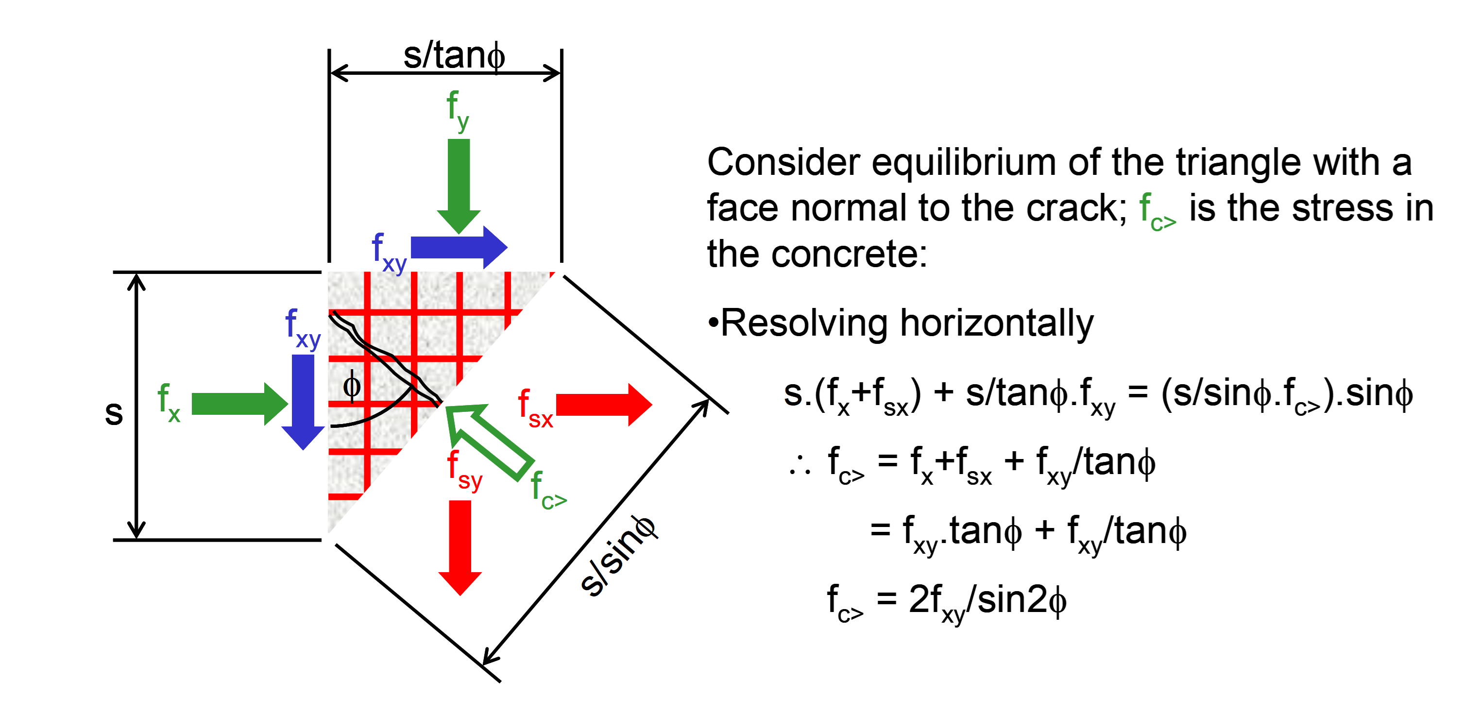
If both and are positive, tensile stress must be taken by reinforcement in both and directions. The lowest total stress is required when equals 45°, for which angle , and .
Mohr’s circles provide a useful tool for determining the stress to be taken by the reinforcement and the maximum stress in the concrete. The circle representing the compressive strength of concrete has principal values of the origin and the concrete design strength. If this circle does not encompass the circle representing the applied stress, reinforcement is required.
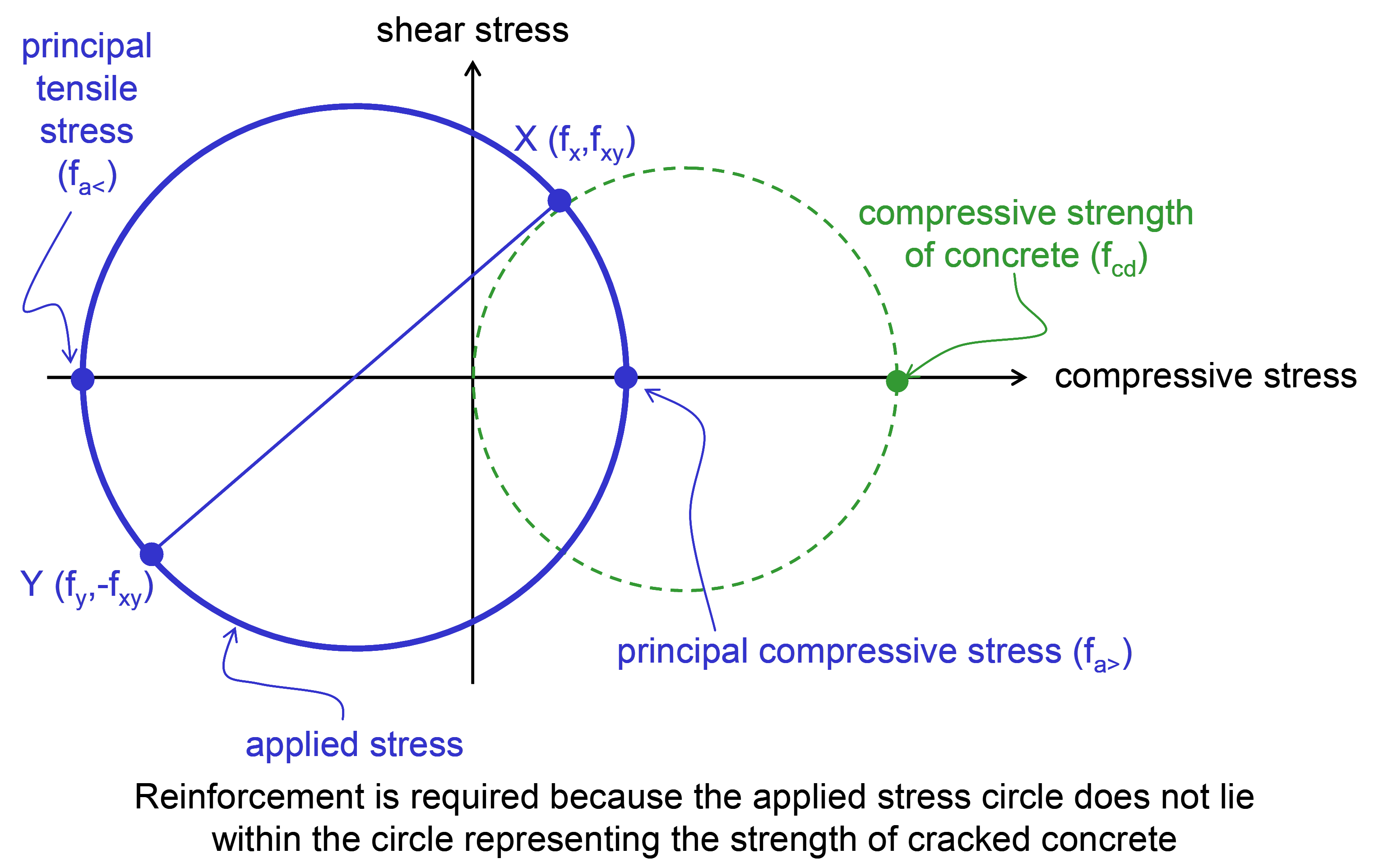
The stress taken by the reinforcement is subtracted from the applied stress to give a residual stress in the concrete, which must always fall within the circle representing its compressive strength. If this is not achievable, then it is not possible to reinforce for the applied stress with reinforcement in the directions chosen; the reinforcement must be orientated closer to the principal directions, or else stronger concrete should be used. If the reinforcement is aligned with the x and y axes, then the offsets representing the stress taken by the reinforcement are horizontal; otherwise the offsets are at an angle with the vertical offsets equal in magnitude but of opposite sign.
Calculation of forces to be taken by reinforcement
Having determined the stresses to be taken by reinforcement in all three layers, the forces in the four sets of reinforcement must be determined considering equilibrium. The differences between the centroids of the stressed layers and the positions of the reinforcement must be taken into account.
If this calculation is undertaken in one stage, anomalies could occur such as tension reinforcement being required where the surrounding concrete is in biaxial compression. To avoid this, the calculation is made in three stages.
The procedure works better if the larger moment results in tension on the bottom. If the larger moment results in tension at the top, the section and applied forces are inverted before the calculation is undertaken, and the results inverted at the end.
In stage A, the forces required in the top steel, , are calculated assuming that the stresses to be taken by the bottom reinforcement are distributed uniformly across the bottom layer, . This is shown diagrammatically below; there would of course be an equivalent diagram for the second steel direction. The overall distribution of concrete and steel stresses in the bottom layer is then rechecked to see whether any of can in fact be resisted by the concrete; this calculation results in stresses of to be taken by the bottom reinforcement.

In stage B, the forces required in the bottom steel, , are calculated returning the top reinforcement forces to stresses distributed uniformly across the top layer, . The overall distribution of concrete and steel stresses in the top layer is then rechecked to see whether any of can be resisted by the concrete; this calculation results in stresses of to be taken by the top reinforcement.

In the final stage, C, any reinforcement, top and bottom, required to take the modified stresses in the top layer is calculated. Considering the top layer last, there will be places where no top steel is required. Although stage C could result in bottom steel in locations where it would be unnecessary with further rationalisation, the reinforcement areas would be small and usually less than nominal bottom steel.

Although this three stage approach calculates reinforcement forces reasonably economically, it may result in small differences in the areas of top and bottom reinforcement for pure axial load.
Determination of section strains compatible with concrete strains in outer layers
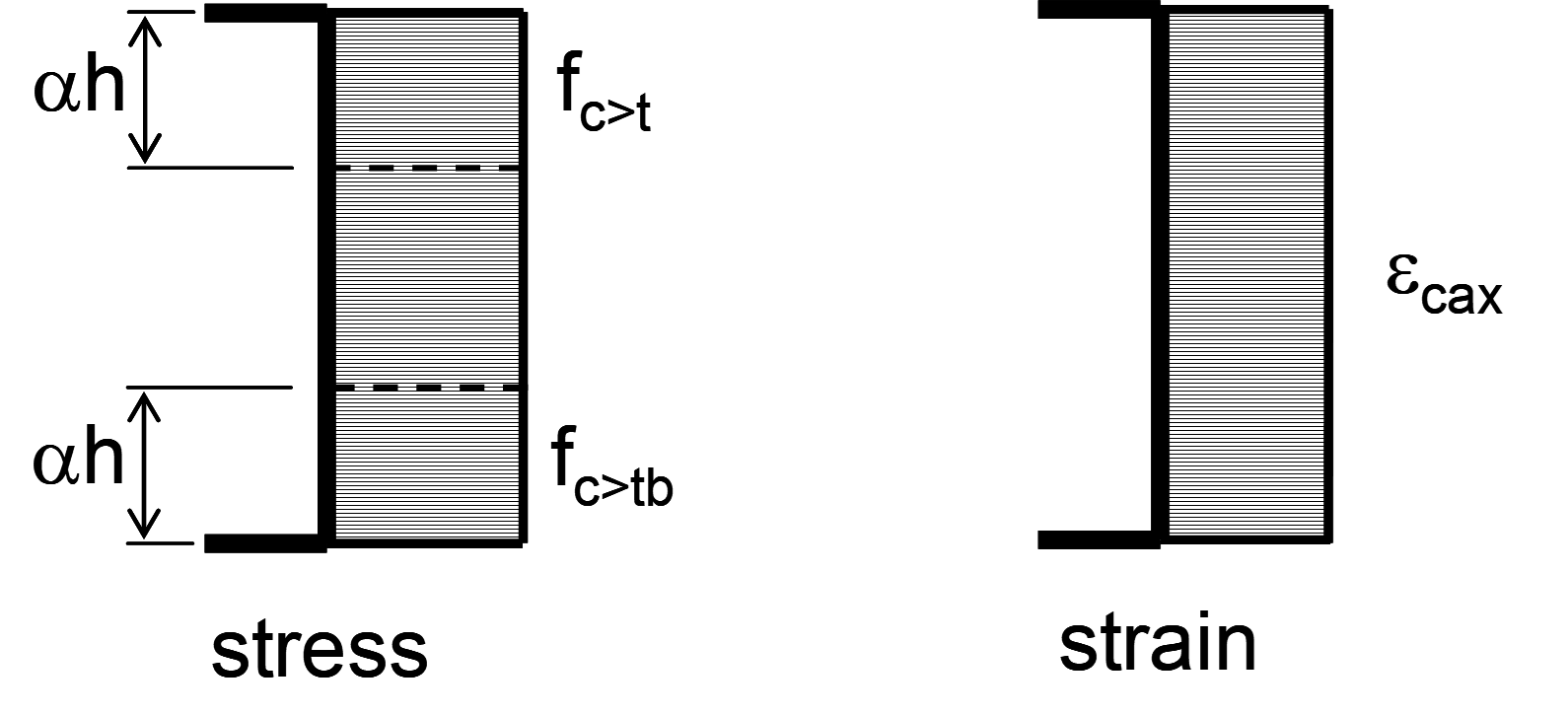
To determine the four sets of reinforcement areas required to take these sets of forces, a design strain, compatible with the concrete stress blocks, is needed for each set. The first stage of calculating these strains is to determine the compressive strains at the outer or inner boundaries of the concrete stress blocks. The calculation of the principal compressive strains at the top is described below; a corresponding procedure is used to estimate the principal compressive strains at the bottom.

Although at this point in the procedure, principal compressive stresses in the concrete have been determined for the top, , and bottom, , layers, the directions of these two principal axes, and , will not generally be aligned. In order to estimate the strain profile for the top layer, , the stress in the bottom layer in the same direction as , is calculated.
Knowing enables the compressive principal strains in the top layer to be calculated.
If then the more compressive strain, , is at the top of the section and taken as the axial limiting strain, .
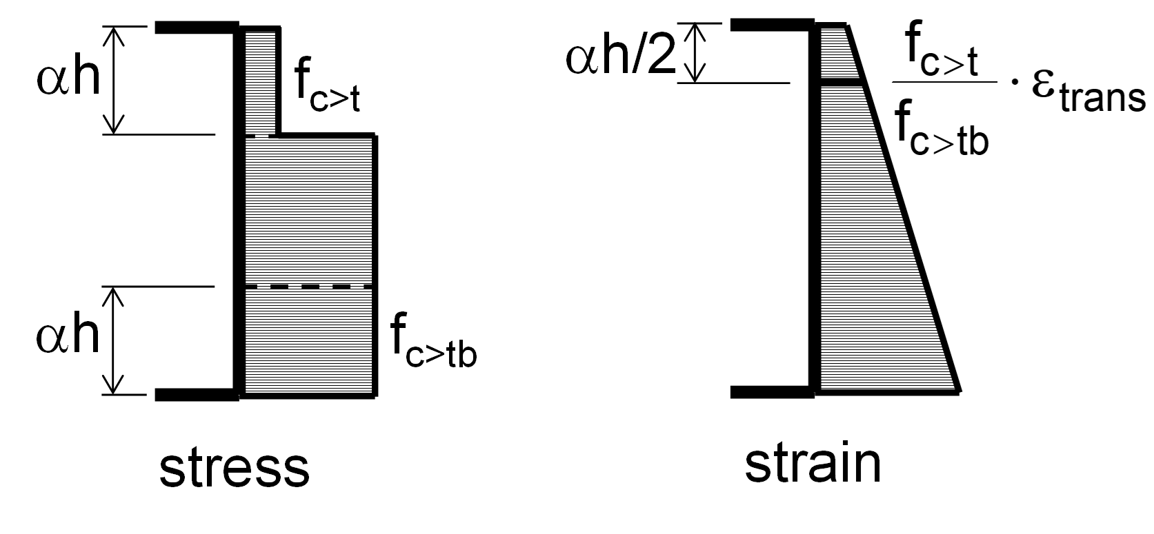
If then is at the centre of the top block and calculated as the compressive plateau strain of concrete, , factored by .
If , is at the top of the section and calculated so that it does not exceed the limiting strain, , and that the axial limiting strain, , is not exceeded at a position from the face, assuming a strain at the centre of the bottom block of factored by .
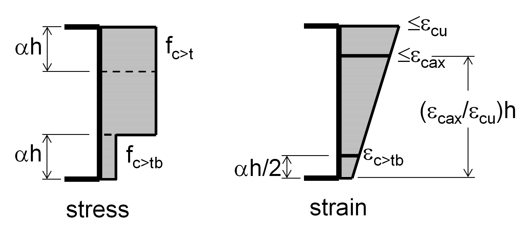
The maximum compressive strain on the more compressed face can exceed even if the maximum compressive stress is less than the concrete strength since the ultimate strain could be obtained with a smaller stress block, , but more favourable lever arm

For all conditions, the less compressive principal strain, , is taken at the same level as . If the less compressive principal stress, , is compressive, then , is taken as factored by , where is the less compressive principal stress in the top block. The key concrete strains are code-dependent.
Determination of compatible reinforcement strains
Having estimated the concrete strains, the next stage is to determine compatible reinforcement strains. There are three different procedures for calculating the reinforcement strains, the choice of which depends on the relations between the reinforcement forces, summarized in the following table. Different procedures may be appropriate for each face and direction.
For directions with flexure, the neutral axis is taken as from the compression edge, where is the ratio of the depth of the rectangular stress block to the depth of the neutral axis, which is code-dependent.

The procedures are described below in detail.
Procedure A
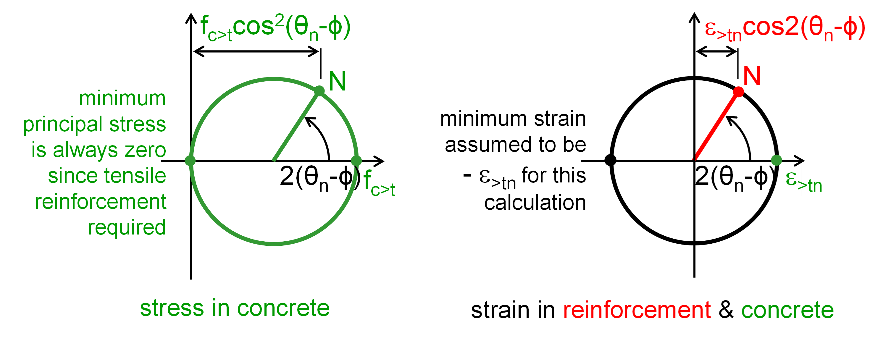
The principal tensile strain is calculated so that the total area of reinforcement in this layer is at a minimum. Note that if the tensile strain is not large enough, the tensile reinforcement will be working at a low stress, or even be in compression, but if the tensile strain is too large, the compressive reinforcement will be working at a low stress, or even be in tension.
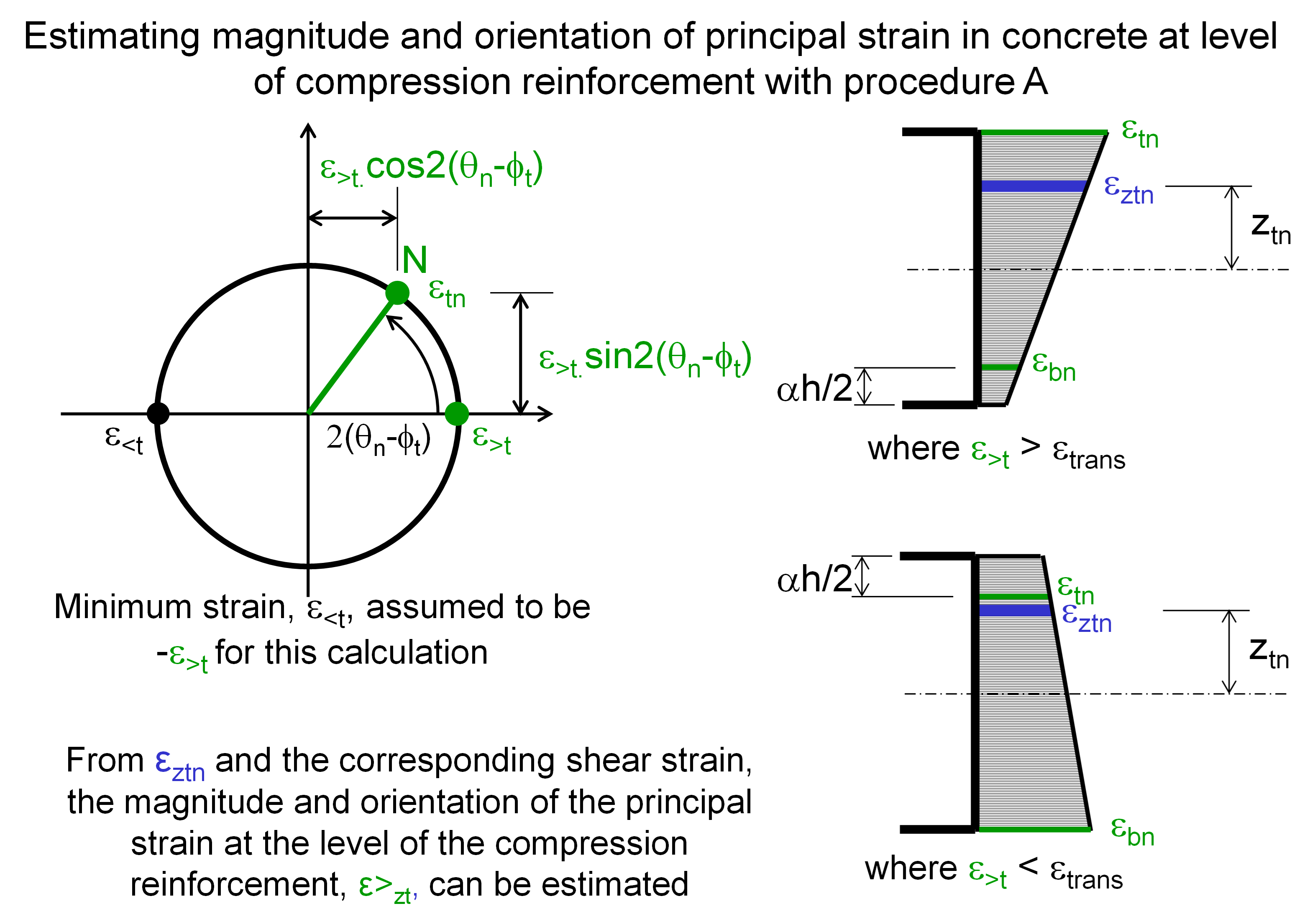
The formulae to calculate the optimum value of the tensile strain are given in Appendix 2. The calculation is made at the level of the compression reinforcement. Although the tension reinforcement will be at a slightly different level, it is assumed that the strain in it is approximately equal to the strain in its direction at this level; since the reinforcement in the opposite face in the same direction will always be in tension, this should be a reasonable assumption.
To estimate the principal compressive strain at the level of the compression reinforcement, the variation in magnitude and direction of the principal compression between the top and bottom layers must be considered. For these preliminary calculations, the magnitude of the principal tensile strain is taken as equal to that of the principal compressive strain. The strains in the reinforcement directions are calculated using the procedure in the figure below for both top and bottom layers at their appropriate block boundary; from these strains, the value at the level of the compression reinforcement is linearly interpolated. From the normal and the shear strains at the level of the compression reinforcement, the magnitude and orientation of the principal strain at this level can be estimated.
The final stage of calculating reinforcement stresses makes allowance for the area of concrete displaced by compression bars by subtracting the concrete stress at the level of the reinforcement from the steel stress. To compensate for this when determining the optimum tensile strain with procedure A, a force, estimated to equal the force in displaced concrete, is added to compressions. This is achieved by factoring the compression by:
Procedure B
This procedure is adopted when strain compatibility is not required for tension reinforcement; the full design strength of the reinforcement is used.
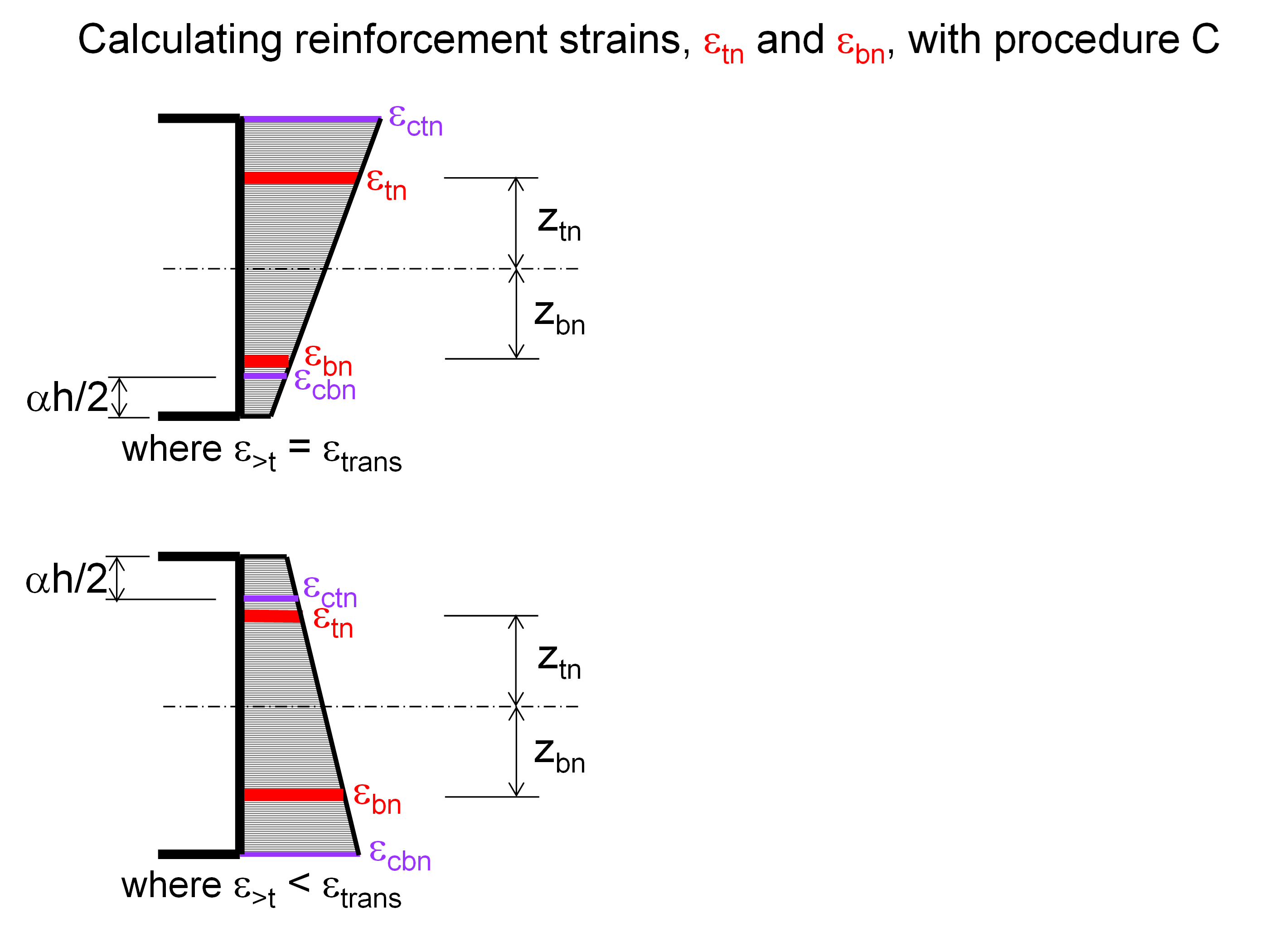
Procedure C
The first stage of this procedure is to calculate the tensile strain in the compression block at either its surface or inner boundary, as appropriate, in the directions of the reinforcement. If the stress block is in biaxial compression, the strain is determined from the concrete stress, but if it is cracked, the strain compatible with the principal compressive strain on the opposite face and the depth of the neutral axis is determined.
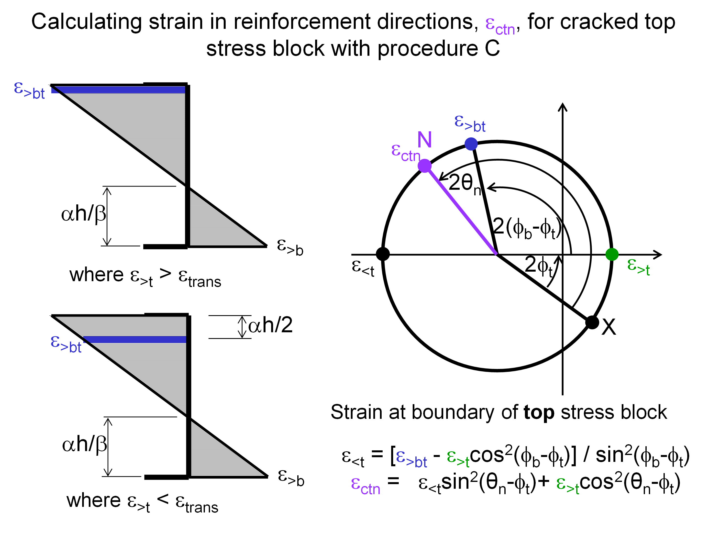
Having obtained the strains in the reinforcement directions at the boundaries of the stress blocks, the strains at the levels of the reinforcement can be calculated.
Determination of stress in reinforcement
The stress in the reinforcement is calculated from the strain; a tri-linear stress-strain relation is used for the reinforcing steel in both tension and compression, for which the salient points are code-dependent. If the bar is to take compression, the calculated stress in the reinforcement is reduced by the layer’s concrete stress in the reinforcement direction to allow for the displaced concrete.
Calculation of area of reinforcement
If the force and stress are of opposite signs then the calculation for this particular value of α is unsuccessful. If the force required to be taken by the reinforcement is of the same sign as the stress calculated in that steel, the area is calculated by dividing the forces by the stress; the area is limited to half the section thickness. The specified minimum area is used as appropriate. Finally, the four reinforcement areas are summed to give a total that is compared with the totals resulting from other iterations: the reinforcement areas with the smallest total are output by the program, with compressive reinforcement identified by negating its area, following GSA’s sign convention.
Non-iterative technique
To speed up the calculation, an option is available, where the loading is primarily either in-plane or out-of-plane, to adopt a non-iterative technique. This approach is likely to lead to slightly more conservative results. The user can choose to use this approach in appropriate situations and can specify a total area of reinforcement, as a percentage of the cross-sectional area, above which a rigorous, iterative solution is used.
Primarily in-plane
The applied loads are taken as primarily in-plane if the eccentricities of the moments equal the minimum eccentricity for each component for which there is a corresponding force.
Where loads are primarily in-plane, is taken as 0.5. If the maximum compressive stress in the layers exceeds its strength, the section is unreinforceable; otherwise, reinforcement areas are calculated.
Primarily out-of-plane
The applied loads are taken as primarily out-of-plane if the more compressive principal is less than . Tensile normal stresses do not prevent use of this technique.
Where loads are primarily out-of-plane, the central layer is unstressed and the value of is initially set to . If the maximum compressive stress in the compressive outer layers exceeds the strength, the section is unreinforceable. If compression reinforcement is required, the iterative solution is used. Otherwise, a reduced value of is calculated so that the relatively more highly stressed of the top and bottom layers is just below its compressive strength, while remaining in equilibrium with the applied moments; limits on the change in are imposed. The stresses are recalculated for this value of , and a further revised value of calculated. If the change in exceeds 0.01, the stresses are recalculated again. Reinforcement areas are calculated for the final value of .
Distribution of reinforcement
RCSlab calculates the area of reinforcement required at each node. Since the reinforcement distribution corresponds to the force and moment distributions with their concentrations and peaks, there may be locations where no satisfactory reinforcement arrangement can be determined because the concrete is overstressed in shear. If these points, which are left black when contouring, are isolated, they can probably be ignored but larger areas will require changes to the geometry or material properties.
It is also usually appropriate to average values of reinforcement in areas of great change. For example, reinforcement requirements in flat slabs can be averaged over the central half of the column strips, the outer portions of the column strips and the middle strips, as when following code methods. It is hoped that future developments within GSA will help automate this averaging process.