Spacer Elements & Sliding Cables
Spacer elements and cable elements are intended to be used as part of multi-noded super-elements or chains in the dynamic relaxation solver. To define the chain, or super-element, the program looks for spacer or cable elements with the same property number, and joins these at common nodes. So all the elements in a continuous length of spacer or cable must have a common property number, unique to that chain.
In other words each super-element is identified by a unique property number. A Super element cannot be discontinuous or bifurcated.
With spacer elements, the order for the input of elements is important as the “ratio” feature adjusts the relative distances between nodes and makes the first element the control: i.e. if the ratio is greater than one, the first element will be the smallest. If it is less than one, the first element will be the largest. The nodes for a spacer element should be defined so that they can be joined together to form a spacer in a head-to-tail sequence.
Generally spacers should not cross each other. If spacers are required in two directions, the spacers in the main direction should be carried through from one edge of a surface to the other and the spacers in the subsidiary direction should join nodes in adjacent main spacers.
Cables and Sliding
Cables are a hybrid form of cable element, intended for use in dynamic relaxation analysis of ‘real’ (not ‘form-finding’) structural models. In this analysis the cable is free to slide at internal nodes where cable element are connected. The cable, composed of a number of cable elements, is considered as a single element in dynamic-relaxation. The cable can freely slide around the internal nodes of the element as if the cable moves around a pulley. As a result, the tensile forces of all the cable elements in a cable are the same. If a clamp is needed along the length of a Sliding Cable, two Sliding Cable elements should be defined, joining at the clamped node.
The cable property is defined by a stiffness per unit length which is equal to where
– elastic modulus
– cable cross section area
The tensile force in the cable is calculated from
in which
is the total unstressed length of the cable
is the total deformed length of the cable
The nodal normal direction in a cable is defined by the line that is within the plane defined by the two legs and it evenly divides the angle composed by the two legs. Only the normal component of force is transferred between the nodes along a cable and the cable.

For the portion of cable shown above assume the cable elements are in the plane.
The cable force is constant along its length. Therefore the components of the cable elements along at node are equal and opposite. And the resultant force in this direction is 0.
The component along is applied to node .
The component along is 0 as the cable is in the plane.
Free spacers and cables can be thought of as opposites in the way in which forces are transferred to their intermediate nodes. Free spacers only apply tangential forces in the plane of the spacer, whereas cables only apply normal forces.
Spacer Elements
Spacers are designed for soap-film form-finding only and it will be ignored in all other analyses even though it may have been defined in the model. In a soap-film, form-finding analysis, spacer elements are used to make up a multiple node super element called spacers. A spacer is used to maintain or adjust the nodal distance along the spacer element chain as desired in the form-found structure. Spacers should lie over 2D element surface or along bar or tie elements with soap-film form-finding properties (i.e. elements with zero stiffness)
All spacers can be considered as chains of bars with initial lengths being set to about half of their actual lengths (to ensure that the Spacers remain in tension under reasonable conditions), the stiffness of spacer elements are defined in spacer properties. To reduce the influence of the spacer elements on the form-found shape of the structure, the stiffness of spacer elements should be as small as possible as long as it can maintain the required nodal spacing. Depending on the spacer type, one or two components of the spacer forces may be suppressed, so spacer elements will only control the nodal spacing and not affect the form-found shape.
As some components of spacer forces are suppressed, the nodes attached to geodesic and free spacer elements are not be in equilibrium at the end of form-finding analysis. In this respect spacers differ from other elements.
There are three types of spacer elements
- Geodesic
- Free
- Bar
The type of spacer element is defined in the spacer properties. They differ in the way that the force exerted by the spacer on the internal nodes is treated. For each internal node, a vector defines which components of the resultant spacer force on the node are taken into account. This force pulls the node along the spacer vector. The remaining components are ignored.
The spacer types also differ in the way in which the spacing rules (defined as spacer leg length type) are applied within the program.
Generally geodesic spacers should be used along 2D element surface. Free spacers should be used to control the nodal spacing along in bar or tie elements. Similar to free spacers, bar spacers can be used to control nodal spacing along bar or tie elements, the difference between free and bar elements is that no component of Bar spacer element forces will be suppressed.
Bar and free spacers simply adjust the spacing of their nodes along the coincident bar or tie elements. Geodesic spacers shift their internal nodes over the surface so as to minimize the overall length between the end nodes (a geodesic is the shortest route over a surface between two points) and also maintain the spacing of their nodes.
To understand the different spacer types, it is useful to consider a short length of spacer chain composed of two spacer elements jointed at the common node.
Geodesic Spacers
For geodesic spacers the component of each spacer node reaction which is normal to the surface of the adjacent soap-film triangle and quad elements is suppressed and so the spacers do not affect the form-found surface; they only control the position of nodes on the surface which is formed. The tension of the geodesic spacers ensures that the spacer nodes shift to form a geodesic upon the soap-film surface that is simultaneously formed by the triangle and quad elements.
The geodesic spacer normal is calculated as follows. The program searches for triangle and quad elements that are connected to the internal nodes of each geodesic spacer and attempts to form a rosette of elements around each node. Failure causes a program error. The nodes of the elements in the rosette are used as ‘control nodes’ to calculate the normal of the surface on which the spacer lies.
Initially, the normal direction is defined from the element geometry of the surrounding 2D elements. This is then adjusted during analysis based on the displacements of the surrounding nodes.
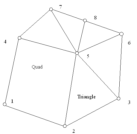
The initial normal of geodesic spacer at node 5 in the above example is equal to
where the are the coordinate of the nodes.
Later in the form-finding analysis, the normal will be rotated based on the displacement of the nodes. The degree of the rotation is calculated assuming all the surrounding nodes (2, 3, 4, 6, 7 and 8) are connected to the spacer node (5) by beams. The beams are pin-connected at the outer side and fixed at node 5. The of the beams is proportional to the sum of the angles each side of the beam. The fixed end moment for each beam at the end of node 5 is calculated. The resultant of the moment at node 5 will rotate node 5, and this rotation will be the one that rotates the spacer normal at node 5.
The normals of the end nodes of a Geodesic Spacer are found (if required) by first computing the normal as for an internal node except that
- The rosette of triangles and quads may be incomplete.
- The current normal is only rotated about an x axis lying in the plane of the normal and the end spacer leg.
The normal of the next internal node is then projected onto the plane of the rotated end normal and the end spacer leg, and reflected about the plane normal to the end spacer leg.
Normals are calculated every 10 cycles.

For the above portion of a geodesic spacer, assume the normal of the plane of soap film triangles and quads joined to node is in the direction. The spacer force applied at node is . So the spacer will move node in the & direction.
The geodesic spacer applies the spacer leg length rules at the start of analysis. The node positions are adjusted at the start of the analysis to meet the rules by factoring the unstressed element lengths. On convergence, the node positions may not meet the leg length rules exactly. If this proves a problem, the use of ‘greasy pole’ restraints or bar spacers could be considered for a final stage form-finding analysis starting from the converged form-found shape. With both options, out-of-balance forces will exist when converting from the soap film to the ‘real’ model, and care is needed in their interpretation.
Free Spacers
For free spacers only the component of a nodal reaction that acts along a spacer’s tangent is preserved. So a free spacer only influences the spacing of nodes, along the length of a 1D form-finding element.
The initial tangent of free spacer at node 2 in the following example is equal to

Note: is the tangent vector at node 2 (= X1). are coordinates of the nodes 1 and 3.
Later in the form-finding analysis, the normal will be rotated according to the displacement of the 3 nodes. The degree of the rotation is calculated assuming nodes 1 and 3 are connected to the spacer node (2) by beams. The beams are pin-connected at the nodes 1 and 3 and fixed at node 2. The of the two beams are equal. The fixed end moment for the two beams at the end of node 2 is calculated. The resultant of the moment at node 2 will rotate node 2, and this rotation is the one that rotates the spacer tangent vector at node 2. The rotation will be about the normal of the plane of the adjacent spacer legs.
The tangents of the end nodes of a free spacer are found (if required) by reflecting the tangent of the next internal node about the plane normal to the end spacer leg. Tangents are calculated every 10 cycles.

For the above portion of free spacer, assume the normal of the plane of the three spacer nodes is in the direction. The spacer force applied at node is . So the spacer will move node in the direction only.
The free spacer applies the spacer leg length rules at the start of analysis. The node positions are adjusted at the start of the analysis to meet the rules by factoring the unstressed element lengths. On convergence, the node positions may not meet the leg length rules exactly. If this is proves to be a problem, consider replacing the free spacer with a bar spacer for a final stage form finding analysis starting from the converged form-found shape.
Bar Spacer
Bar spacer should run parallel to 1D tie elements with soap-film properties, and the two elements should have common nodes. No component of a bar spacer force is suppressed so a bar spacer influences the spacing of nodes, along the length of the soap-film tie, and the position of the soap-film tie. The soap-film tie has zero stiffness, but the bar spacer has a small stiffness. Therefore forces may vary along the bar spacer. To maintain equilibrium post form-finding, bar spacer forces should be added to the tie pre-stress in the final model as spacer elements are only considered during form-finding analysis. The effect of the bar spacer on the final form-found shape increases with the bar spacer stiffness.
The bar spacer is, in effect, a multi-noded bar super-element, or chain, with a low stiffness that complies with spacing rules for the nodes along its length (defined by the spacer leg length type)

For the above portion of bar spacer, assume the normal of the plane of the three spacer nodes is in the rection. The spacer force applied at node is . So the spacer will move node in the and direction.
The bar spacer applies the spacer leg length rules by repeated analysis. The node positions are adjusted at the start of the analysis to meet the rules. On convergence, the node positions are adjusted along the length of the bar spacer, and the analysis repeated. This continues until the spacing rules are met.
The position of the nodes is adjusted by factoring the unstressed element lengths.
Spacer leg length type
There are three rules, or options, to control nodal spacing along a spacer, which can be selected when defining the spacer properties. These spacing rules are proportional, ratio, and projected ratio. Free and Geodesic spacers apply these rules to the initial leg length at the start of analysis but do not recheck on convergence. For spacers included in soap film structures, the ratio of the final leg length to the initial leg length will be approximately constant and the spacing rules will be met approximately. However if varying point loads or other constraints are applied along the length of the spacer the final spacing may be too approximate to be satisfactory. In this case the use of a Bar Spacer may be considered. For Bar Spacers, the spacing rules are checked on convergence, and the analysis is repeated until the leg length rules are met exactly.
The three options offered as leg length type are:
- Proportional – the final length of the spacer legs will be proportional to their original length. To achieve this, the initial length of each spacer leg is set to half the initial distance between end nodes.
- Ratio – the spacer leg length ratio will be equal to that specified, e.g. if the ratio is specified as 2, the final leg length of the 2nd element will be twice as long as the leg length of the 1st and so on. If a ratio of 1 is specified, the initial length of all the spacer legs will be made equal.
- Projected-ratio – Specify an axis set in the spacer property table. If a user defined axis set is not specified, the global axis set will be used. The spacer legs are projected onto the x-y plane of the specified axis set. The program adjusts the initial length of the spacer such that the projected length of each spacer leg on the x-y plane follows the specified ratio rule. If a ratio of 1 is specified, the projected length of all legs will be equal. If a ratio of 2 is specified, the projected leg length of the 2nd element will be twice as long as the projected leg length of the 1st and so on.