Elements
An Element is an entity that is analysed. Its topology and position is defined using Nodes and Offsets. Its orientation is defined by the element axis set which depends on the topology of the element and the orientation node and angle. Its end fixity is defined partly by the behaviour of the Element Type and partly by the element Releases.
Elements can be created via the Element wizard or via the data tables.
The types of element offered depend on the structure type specified. The definition of the element behaviour varies with the solver chosen in the Analysis Wizard.
Each element is assigned a property number and a group number. The property number is used to assign stiffnesses, material and other relevant properties to the element in the appropriate properties table. The group number can be used for data management.
In general Elements are treated as individual entities. However there are two element types that are treated as a linked set of entities during analysis. These are Spacer and Cable Elements. The GsRelax solver will link adjacent Spacer or Cable elements together to form a chain.
Any element can be made into a dummy element to result in it being ignored during analysis. The dummy attribute can be set in the Element Wizard or graphically using the Sculpt command to Modify Elements.
Elements should not be confused with members, which are used for design.
Definition
Element Type
Sets the element type. The element types are:
- 1D – Beam Bar, Rod, Tie, Strut, Cable, Spring, Damper, Link, Spacer
- 2D – Quad 4, Quad 8, Triangle 3, Triangle 6
- 3D – Brick 8, Wedge 6, Pyramid 5, Tetra 4
Dummy Element
When checked, the element is specified as a dummy element and is ignored during analysis.
Beam Section or Element Property
This item is labelled according to the element type. It specifies the properties that are used for analysis to determine the stiffness and mass matrices. Either choose a property from the list or type in a property number.
Property
The property number defines which properties relate to a particular element. The property table to which this item points will depend on the element type. Each of the property tables starts with Property Number 1.
- Beams, Bars, Ties and Struts reference Beam Sections
- Springs reference Spring Properties
- Dampers reference Damper Properties
- 2D elements reference 2D Element Properties
- 3D elements reference 3D Element Properties
- Link elements reference Link Element Properties
- Cable elements reference Cable Properties
- Spacers reference Spacer Properties
Note that each complete linked chain of spacer elements should have a unique spacer property number. This number should be given to each of the individual 2-noded spacer elements that make up the chain.
An element can have more than one property definition for form-finding analysis. These are all defined using the same Property number.
For example if a bar is given property number 3 in the Elements Table all analysis solvers will normally look for Property 3 in the Beam Sections property table for the required physical properties of the bar. However, if the analysis selected is soap film form-finding, Property 3 in the 1-d soap-film form finding properties table will be used instead if information has been input. Similarly, if the analysis selected is force-density form-finding, Property 3 in the 1-d force-density form finding properties table will be used instead if information has been input.
Beams, bars, ties, struts and 2D elements that require material definitions reference these through the relevant property table.
Group
The user can split the structure into Groups of elements, which can be used to:
- attribute element loads to particular group(s).
- reduce the quantity of tabular output or clarify plots, when only nominated group(s) are shown.
Topology
All elements are located in space through the nodes to which they attach. The number of nodes defining the topology depends on the element type:
- beams, bars, ties, struts and springs have two topology items;
- 2D elements, (depending on the element type), will have 3, 4, 6 or 8 topology items;
- 3D elements will have 8 topology items.
For 1D elements the order in which the topology is defined will determine the local x direction. For link elements the first node in the topology list becomes the primary node. In the Gss solver this implies a constraint on the other (constrained) node.
For 2D elements the topology order is anti-clockwise when looking on the top surface of the element. All the corner nodes are identified first, followed by the mid-side nodes. The local axes of a 2D element will depend on the topology order unless overridden by the axis in the “2D Element Properties”.
For 3D elements the topology order is anti-clockwise when looking on the top surface of the element. The four lower corner nodes are identified first, followed by the upper corner nodes. The local axes of a 2D element will depend on the topology order unless overridden by the axis in the “2D Element Properties”.
Orientation
The orientation information is used to establish the local axes of an element. The definition of the element axes depends on the element type, the orientation node and the orientation angle. The angle is measured in degrees.
Both orientation node and angle are used to define the orientation of beam, bar, tie, strut and spring, damper elements for which the spring property axis is set to local. The orientation angle is used to define the orientation of the 2D elements, but this can be modified by the 2D element axis defined in the “2D Element Properties”. Link, cable and spacer elements use neither orientation node or angle to define the orientation.
Note for fabric 2D elements the warp axis aligns with the element local x axis.
Offsets
The flexible part of an element may be offset from the nodal positions by specifying an offset. Offsets may be used where the flexible part of an element is less than the full length of the element or where the centreline of the element does not coincide with the line between the nodes at each end. For example where a beam is connected to a large column, it may be desirable to offset the flexible part of the beam by half the column width from the node. Offsets are treated as rigid arms between the node and the flexible part of the element.
Offsets are specified in local axis directions.
Care should be exercised before using offsets to ensure that this feature is appropriate. Offsets cannot be used in GsRelax and attempts to use them will result in an error message.
Translational and Rotational Releases
By default, Beam and 2D elements transfer moment to nodes and adjoining elements; releases may be applied to these elements to allow free rotational movement.
Releases may be set for each element axis direction, for each topology item.
Releases may be applied only to Beams.
A release on an offset element is located at the offset position, not at the node.
On beams:
Each degree of freedom at each end of the beam element can be released. If the degree of freedom is released a stiffness can also be applied to connect the end of the beam to the node.
The dropdowns give shortcuts to setting up common release options.
Fully fixed – the end of the beam is not released in any direction
Release translations – the translation degrees of freedom are released, allowing the end of the element to translate freely, but the rotations are still fixed to the rest of the structure
Release moments – the moment degrees of freedom are released for the element, but translations are still fixed to the rest of the structure
Remove stiffness – the releases are retained but the stiffnesses are removed.
Note: care should be taken when applying releases that the resulting element does not become unstable. Various checks for invalid restraints are carried out to prevent singularities at a later stage in the analysis. It is invalid to:
- release a translational degree of freedom at both ends of a beam
- release the torsional degree of freedom at both ends of a beam
- release moment degree of freedom at both ends of beam and one of the corresponding translational releases
Note that releasing the x axis at both ends of a beam element will result in an element free to spin about its axis. Where a fully released beam is required it is usually preferable to use a Bar element.
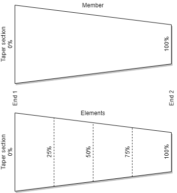
Tapered 1D elements
A 1D element can taper between end 1 and end 2 if it uses a section defined for tapering elements, where two section sizes are defined within one section profile. See Section Profile definition for how to create them.
As multiple elements can be created from a single tapering member, each element needs defining based on the original member section in such a way that each element has the correct dimensions. This is achieved using the taper offset, which ensures that the element has the correct section size from that portion of the member.