Raft Analysis
Raft analysis is a soil-structure interaction analysis, iterating between a solution of the structural problem and the soil problem until convergence of nodal displacements is achieved.
Iteration
For the soil interaction nodes on raft, the analysis iterates through the following steps until convergence is reached:
- For each soil interaction node, a spring support will be generated with default support stiffness it does not exist. If the support spring exists, it will be used and its stiffness will be modified during the analysis. After analysis, its stiffness will be restored.
- Run linear static analysis to obtain the displacements and spring-support forces for each of the interaction nodes
- Calculate soil pressure under each of the soil interaction nodes using Where is the area associated with interaction node and the contact pressure is subject to lower and upper limits .
- Run soil analysis to obtain the settlements of soil, under the applied pressure loads
- Check the differences between raft displacements and soil settlements, if they are smaller than the residual limit, save the results and stop the analysis, otherwise go to step 6
- Re-calculate the support spring stiffnesses according to the support spring forces and the soil settlements using the following equation and go to step 2.
A damping coefficient that can be used to modify the stiffness update, i.e. reserve some percentage of the previous stiffness. The value of damping coefficient is between 0 and 1. If damping coefficient is specified, the new stiffness will be calculated from:
Piles
For the soil interaction nodes on the piles, the analysis iterates through the following steps until convergence is reached:
-
For each soil interaction node, generate a spring support in x, y and z directions with support stiffness calculated from soil settlement under unit point load.
-
Run linear static analysis to obtain the displacements and spring-support forces for each of the interaction nodes
-
Calculate the soil reaction forces to the interaction nodes from
where the interaction areas for the interaction node are
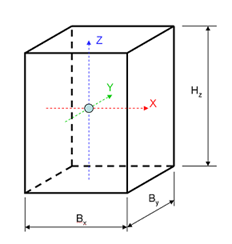 (Pile interaction node and relevant dimensions)
with the perimeter of the pile and where
(Pile interaction node and relevant dimensions)
with the perimeter of the pile and whereand , , are the pile soil interaction coefficients and derived from the pile soil interaction coefficient (PSIC) curves defined by the users as shown below.
 (Pile Soil Interaction Coefficient Curve)
where is the differences of the pile displacements and the
soil settlements at the corresponding points and is the pile
dimension , in x and y directions or diameter.
(Pile Soil Interaction Coefficient Curve)
where is the differences of the pile displacements and the
soil settlements at the corresponding points and is the pile
dimension , in x and y directions or diameter. -
Calculate the pressure loads on soil due to the soil reaction forces and the interaction areas
-
Run a soil settlement analysis using the embedded Pdisp program
-
Calculate the compensation forces to counter balance the support spring forces due to the use of constant support spring stiffness.
-
Check convergence, if satisfied, stop, otherwise, go to Step 2.
Convergence
The solution is converged if the difference of raft/pile displacements and soil settlements are smaller than the predefined acceptable residual. The residual can be defined in two ways.
- Absolute residual - the residual is defined directly such 0.1 mm, 1.0 mm, or 5.0 mm.
- Relative residual - a percentage is defined that is used to calculate the actual residual based on the largest soil settlement. The actual residual is equal to the defined percentage of the largest soil settlement.
See also Raft and piled-raft analysis steps for a how to guide and more information on performing this analysis type.