Raft Analysis
Raft analysis is a soil-structure interaction analysis, iterating between a solution of the structural problem and the soil problem until convergence of nodal displacements is achieved. See Raft analysis (Theory) for more information on how GSA iterates for a solution.
The following guide shows how to set up a raft analysis as well as a piled raft analysis.
Raft analysis
The following are the main steps required for performing a raft analysis.
-
Build up a raft model, the raft can be modelled by a grillage using beam elements or by a horizontal plate using 2D elements.
-
Define loads on the raft as usual in GSA. See also the tutorial on Loading for how to apply loads.
-
Open Raft analysis specification dialog box from Data explorer > Specification > Raft analysis to define rigid boundary level and soil settlement analysis parameters.
-
Open Soil profiles table from Data explorer > Raft > Soil > Soil profile to define soil properties. A single soil profile defines the soil properties in a vertical line from the top surface of the soil to the rigid boundary level below. A soil profile may include properties of many layers depending on the real soil conditions. There is no limit to the number of soil profiles defined as this depends on the actual site requirements. Once defined, soil profiles are assigned to rectangular areas called soil zones.
-
Open Soil zones table from Data explorer > Raft > Soil > Soil zones to assign soil profiles (properties) to relevant rectangular areas called soil zones. If soil zones are overlapped, the overlapped areas will use the soil profile as defined in the soil zone table.
-
To define the nodes on raft to interact with the soil, open Raft interaction table from Data explorer > Raft > Raft interaction. The interaction areas of the raft interaction nodes can be defined on this table or GSA can calcuate them when the value under Automatic is yes. The elevation of the interaction can also be defined here or enter yes under Automatic to take the nodal z coordinate as the interaction elevation. Minimum and maximum soil pressure can also be defined in this table. Zero minimum soil pressure means that soil will not take any tensile stresses. If minimum soil pressure is defined by a negative value, the soil tensile strength will be used. The maximum soil pressure is the compressive strength of soil. If this pressure is reached during the analysis, the soil-raft contact pressure will not increase any more to allow soil local yield effect to be considered.
-
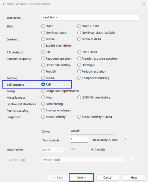
Now we are ready to do raft analysis by going through the Analysis wizard. As with other analysis types in GSA, start from menu Analysis > New analysis task to open the Solver option dialogue.
-
Under Soil-structure, select Raft and click Next to define the Analysis options.
- From the Soil structure analysis dialogue, define options including maximum number of iterations, PDisp analysis, Displacement residual and Force residual values.
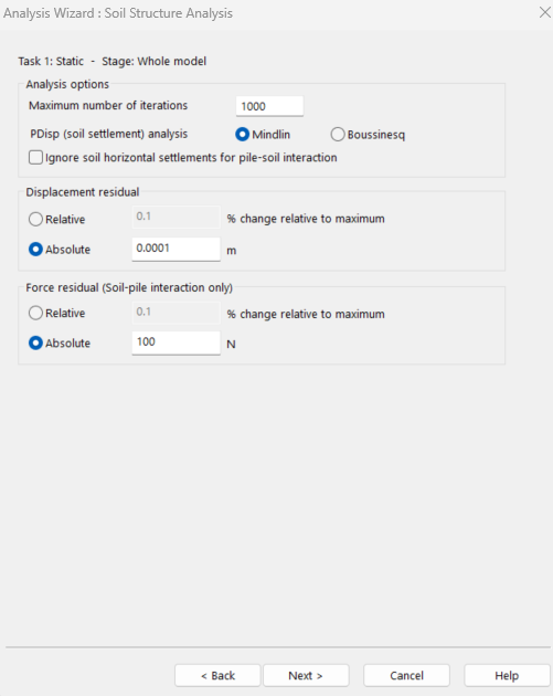
Note: The data described in the above steps are always required for raft analysis. There are other data such as PDisp, which are not always required in most of the raft analysis.
The following describes how to account of soil nonlinearity and rectangular soil loads in a Raft analysis.
Nonlinear curve
If soil nonlinearity needs to be considered and the soil strain - Young’s modulus (or Young’s modulus reduction factor) relationship is known, the nonlinear curve defining the strain - Young’s modulus reduction factor can be defined and then referred to by the relevant soil profile. Once this has been done, the soil Young’s modulus will be changing according to the current soil strain so nonlinear properties is considered. This is nonlinear curve is only used when Boussinesq is selected for soil settlement analysis.
Soil rectangular load
The loads defined in the Soil rectangular load table are the loads acting directly on the soil in addition to those loads from the raft. Normally, these loads are not required as the soil loads from raft are defined as raft loads. The loads on raft will be transferred to soil through the interaction nodes during the analysis. If there are additional loads directly on the soil, e.g. construction loads acting on directly on soil outside the building, they can be defined in this step to increase the flexibility of GSA raft analysis.
Piled-raft analysis
The following highlights the required steps for building and modelling a piled-raft analysis.
-
Build up a piled-raft model, the raft can be modelled by a grillage using beam elements or by a horizontal plate using 2D elements. A pile should be modelled by a number of vertical beam elements. The number of beam elements used to model a pile depends on the length and section size of the pile since pile-soil interaction is defined by the nodes on the pile. Normally, 10 beam elements may be required to model a single pile.
-
Define loads on the raft as usual for analysis setup in GSA. For more on this step, see our section on Loading. Loads acting on a pile directly can be defined using beam loads.
-
Open Raft analysis specification dialog box from Data explorer > Specification > Raft analysis to define rigid boundary level and other soil settlement analysis parameters.
-
Open Soil profiles table from Data explorer > Raft > Soil > Soil profile to define soil properties. A single soil profile defines the soil properties in a vertical line from top surface of the soil to the rigid boundary level below. A soil profile may include properties of many layers depending on the real soil conditions. There is no limit for the number of soil profiles to be defined as this depends on the actual site requirements. Once defined, soil profiles are assigned to rectangular areas called soil zones.
-
Open Soil zones table from Data explorer > Raft > Soil > Soil zones to assign soil profiles (properties) to relevant rectangular areas called soil zones. If soil zones are overlapped, the overlapped areas will use the soil profile defined in the soil zone table.
-
Open Pile-soil interaction properties table from Data explorer > Raft > Soil > Pile-soil interaction properties* to define the pile-soil interaction properties. The properties include the maximum soil stresses (strengths) at the top and bottom of each soil layer in X, Y & Z directions as well as at the pile base. The interaction in X, Y & base are normal contact strength and the interaction in Z is shear strength between pile surface and soil in vertical direction. A Pile-soil interaction property is referred to by one or more soil layers in the soil profile table. The pile-soil interactions are nonlinear these relationships are defined by Pile-soil interaction coefficients which is a curve defining the relationship between normalised relative soil pile displacements and the reduction factor of the soil strength. Which Pile-soil interaction coefficients (curves) to be used for this pile-soil interaction in X, Y, Z & base need to be defined in this table as a reference to the Pile-soil interaction coefficients table.
-
Open the Pile-soil interaction coefficients table from Data explorer > Raft > Soil > Pile-soil interaction coefficients to define the pile-soil interaction coefficients (curves). These coefficients (curves) define the relationship between the normalised relative soil-pile displacements and the reduction factor of the soil strength and are used (referred to) by the pile-soil interaction properties.
-
To define the nodes on raft to interact with the soil, open Raft interaction table from Data explorer > Raft > Raft interaction. The interaction areas of the raft interaction nodes can be defined on this table or GSA can calculate them when the value under Automatic is yes. The elevation of the interaction can also be defined here or enter yes under Automatic to take the nodal z coordinate as the interaction elevation. Minimum and maximum soil pressure can also be defined in this table. Zero minimum soil pressure means that soil will not take any tensile stresses. If minimum soil pressure is defined by a negative value, the soil tensile strength will be used. The maximum soil pressure is the compressive strength of soil. If this pressure is reached during the analysis, the soil-raft contact pressure will not increase any more to allow soil local yield effect to be considered.
-
Open Pile interaction table from Data explorer > Raft > Pile interaction to define the nodes on piles to interact with soil. The interaction areas of the pile interaction nodes can be defined on this table or or GSA can calculate them when the value under Automatic is yes. The elevation of the interaction can also be defined here or enter yes under Automatic to take the nodal z coordinate as the interaction elevation. Normally the elevation of soil pile interaction should be calculated automatically as pile interaction nodes are not at the same level.
-
Now we are ready to do piled-raft analysis by going through the Analysis wizard. As with other analysis types in GSA, start from menu Analysis > New analysis task....
See also: Notes on raft analysis.