Nonlinear buckling analysis
This analysis is performed using the nonlinear static analysis option in GSA, which uses the dynamic relaxation solver. For some structures buckling doesn't happen suddenly and can be preceded by a gradual reduction in stiffness as forces increase. The dynamic relaxation solver recalculates element forces and overall model stiffness based on the deformed geometry, therefore P-delta effects and the reduction in stiffness associated with the onset of buckling is considered automatically. In addition, the stiffness of individual beam elements is reduced when they are in compression.
The automatic load increment option in nonlinear static analysis could be used to search for the collapse / buckling load of a model, starting from a predefined first increment. Note that the loads are increased monotonically in this analysis.
1. Setting up the model
Create a new GSA file or open an existing model. Create members, elements, nodes, restraints, etc. as per usual keeping in mind the following implications for buckling analysis.
1D elements
Beam elements should be used if buckling within the element need to be considered. Bars and struts will not buckle no matter how large the compressive forces.
Restraints
It is advised to use nodal restraints. As buckling effects are three dimensional, it is inadvisable to define global restraints on the structure, as this can potentially provide an artificial degree of stiffness to the model. To add nodal restraints, Select Nodes and modify supports conditions from: Properties pane > Restraints.
Releases
Add releases to the start / end of one element in order to transfer / not transfer bending moment. Go to Properties pane > Releases.
Meshing members
In order to capture buckling within a single member it is advisable to mesh it so that there are at least two elements per member.
To change the mesh size, select the member and go to the Properties pane to modify the analysis element size.
To generate analysis elements from the members, use the Create elements from members tool from Model > Coordination tools > Create elements from members or use the toolbar shortcut.
Checking the model with a linear buckling analysis
There are a number of nonlinear analysis options that can be used to investigate the behaviour of a structure as it approaches its first mode of buckling. It can be helpful to run the model through the modal buckling analysis first to get an estimate of the buckling load factor, then create a new model with imperfections introduced based on the first mode shape.
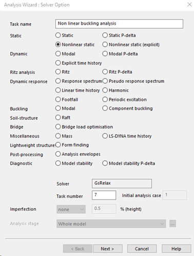
2. Setting up a nonlinear static analysis task�
To perform a nonlinear buckling analysis, a nonlinear static analysis task is needed.
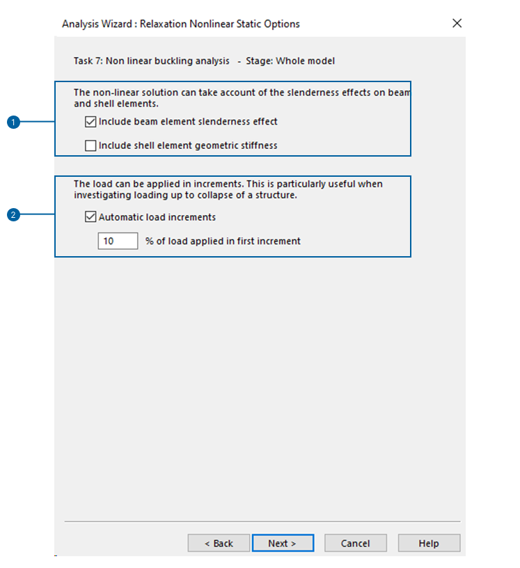
Analysis parameters
-
Include beam element slenderness effect: When checked, slenderness effects on individual beam elements are included by the use of stability functions. These avoid the need to include intermediate nodes in beam elements to consider their stability.
-
Include shell element geometric stiffness: When checked, the geometric stiffness of each shell element is included in the shell element stiffness matrix.
-
Automatic load increment: When checked, the magnitude of each load increment (except the first increment) will be chosen automatically by the program. The load applied in the first increment is specified as a percentage of the total imposed loads.
If unchecked, a nonlinear analysis without load increments is performed. In other words, a static analysis with geometrical nonlinearity and defined load cases is performed. This could be necessary in specific applications, but is not what is required for buckling analyses.
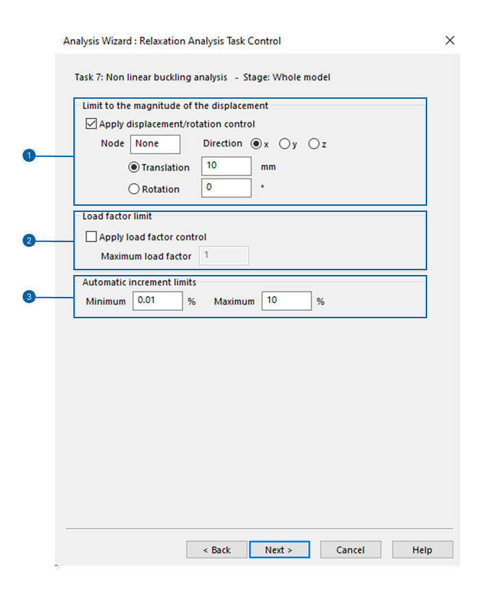
During the analysis, the loading is increased until the specified limits are exceeded.
- These limits can be expressed in terms of nodal displacement (translation or rotation).
- These limits can be expressed in terms of load factor.
- The size of each increment can range between a minimum and maximum limit.
The program gradually increases the load factor. It decides how much to increase the load automatically based on the likelihood of convergence in the previous step: if the last step was easy to converge, the current step will have a larger increase, and vice versa. If the analysis fails to converge at the current load increment, it reduces the interval until convergence is achieved or the minimum specified increment is reached. Once the minimum is reached, the analysis stops, indicating that the current load level represents the model's likely ultimate capacity.
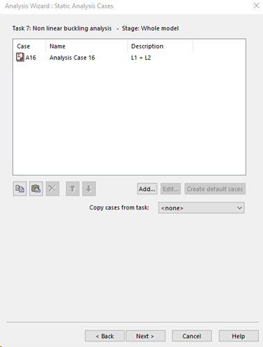
Analysis cases
In nonlinear analysis, the connection between load and deformation isn't linear. Consequently, load cases must be explicitly defined within the analysis, and the results can't be extrapolated later by simply adding up the effects of different loads linearly.
3. Results evaluation
The results of the nonlinear buckling analysis (nonlinear incremental analysis) and corresponding displacements are available after the analysis from the Output tab of the Explorer pane and selecting Global results > Load factor / Displacement relationship output.