Working with the property pane
The Property pane is a dockable ane that allows you to view and modify the default and current settings of entities, such as nodes, elements, and members. It will show the defaults for any new entity if nothing is currently selected, or it will show the current properties of any entity that is selected. If you select multiple entities then it will show the properties that are common between them, and show <varies> for those that differ.
Node properties
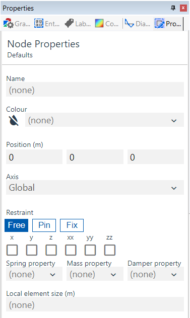
The Node properties pane allows you to set the defaults or edit the properties of selected nodes. See Nodes for more information.
| Field | Description |
|---|---|
| Name | Text used for easy identification. |
| Colour | Select from list. |
| Position | Coordinates; existing nodes only. |
| Axis | Select from list of Axis sets to set the node's Constraint axes. |
| Restraint directions | Choose your structural support type. |
| Spring property | Gives the node a spring restraint. Select from the list generated in the Spring properties table. |
| Mass property | Gives the node an additional mass. Select from the list generated from the Mass properties table. |
| Damper property | Gives the node a damping value. Select from the list generated from the Damper properties table. |
| Local element size | Adjusts the local mesh density of a connected member. Note that it only affects 1D members if the member element size is anything other than 'none'. |
Element properties
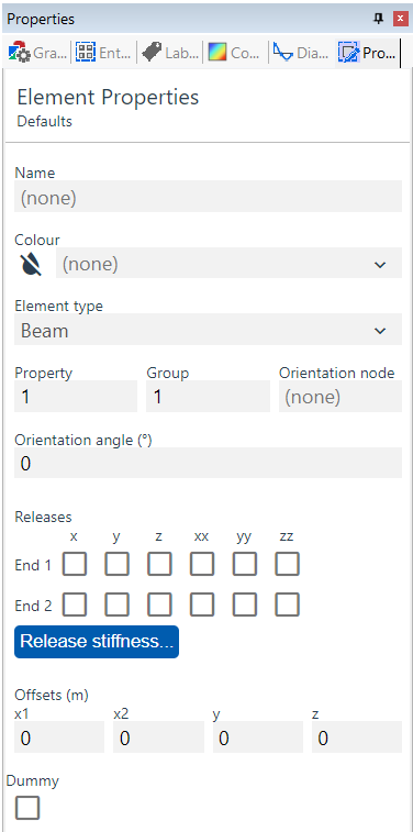
The Element properties pane allows you to set the defaults or edit the properties of selected elements. See Elements for more information.
| Field | Description |
|---|---|
| Name | Text used for easy identification. |
| Colour | Select from list. |
| Element Type | Select from list; see Element types for more details |
| Property | Select from list defined in Properties : Section, Spring properties, 2D element properties, 3D element properties, Link properties, Cable properties, Damper properties, or Spacer properties tables, dependant on the Element types chosen above. |
| Group | A user-defined number to aid loading and output; see Output by case, property, or group, or Colour in graphic views for more details. |
| Orientation node | Input node number; see Element axes for more details. |
| Orientation angle | Input rotation angle in degrees; see Element axes for more details. |
| Releases | Partially disconnect elements from others; 1D elements only; see Elements for more details. |
| Release stiffness | Partially disconnect elements from others; 1D elements only; see Elements for more details. |
| Offsets | Distance elements from others; see Elements for more details. |
| Dummy | Elements that are ignored during analysis but can help with area loads; see Elements, 2D loads on load panels, and Modelling implications for more details. |
Member properties
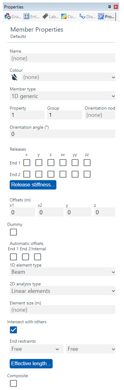
The Member properties pane allows you to set the defaults or edit the properties of selected members. See Members for more information.
| Field | Description |
|---|---|
| Name | Text used for easy identification. |
| Colour | Select from list. |
| Member type | Set the member to be 1D, 2D, or 3D. |
| Axis | Select from list of Axis sets. |
| Property | Select from list defined in Properties : Section, Spring properties, 2D element properties, 3D Element properties, Link properties, Cable properties, Damper properties, or Spacer properties tables, dependant on the member type chosen above. |
| Group | A user-defined number to aid loading and output; see Output by case, property, or group, or Colour in graphic views for more details. |
| Orientation node | Input node number; see Element axes for more details. |
| Orientation angle | input rotation angle in degrees; see Element axes for more details. |
| Releases | Partially disconnect resulting end elements from others; 1D members only; see Elements for more details. |
| Release stiffness | Partially disconnect resulting end elements from others; 1D members only; see Elements for more details. |
| Offsets | Distance elements from others; see Elements for more details. |
| Dummy | Elements that are ignored during analysis but ; see Elements, 2D loads on load panels, and Modelling implications for more details. |
Member properties: Automatic offsets
| Field | Description |
|---|---|
| End 1, End 2 | Offset 1D member and resulting 1D elements from connected 1D elements. |
| Internal | Offset 2D member resulting elements to face of 1D column and connect with a rigid constraint. |
| 1D element type | That will be created when the 1D member is meshed, select from list; see Element types for more details. |
| 2D analysis type | That will be created when the 2D member is meshed, select from list, see Element types and Rigid constraints for more details |
| Element size (m) | Sets the size of the resulting elements when the member is meshed, see Members and element meshes for more details; if set to none and 1D then there will be no additional meshing other than that derived from the connecting members; if set to none and 2D or 3D then the default element size will be 1m. |
| 2D meshing mode | Applicable to 2D members, this sets how the member is meshed. Options are "Tri only" (for all triangle element mesh), "Mixed" (for mixed quad/tri element mesh, with a preference for quad elements) and "Quad only" (for all quadrilateral element mesh) |
| Intersect with others | The member will mesh with other members that overlap with it; eg untick for Crossed tie bracing or Load panels to prevent unwanted subdivision of resulting elements. |
| Design options for effective length | Determine how 1D member effective lengths are determined for design calculations; see Generating steel member restraint for more details. |
| Design variable overrides | Allow steel design calculation variables to be overriden. The availability of these inputs depends on the selected steel design code. |