Beam loads
Beam Loads are a ways of applying load to beam members and elements offering the commonly used load patterns as different types. When loads are applied to members, they will be automatically expanded to load the appropriate finite elements.
All these loads except the point load type are distributed along the members or elements. If the beam has offsets the load positions relate to the flexible part of the beam, not the node positions.
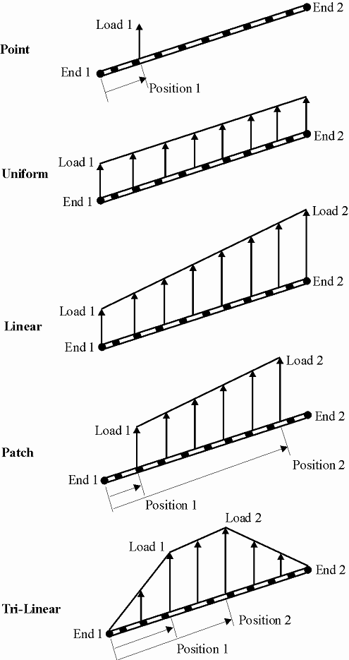
The various types of beam loads are illustrated as follows.
Beam loads can be applied in local (i.e. element axis), global or user defined axis directions. User axes can only be Cartesian; not cylindrical or spherical.
Beam loads offer the option to specify the load as a projected load. When projected is set, the distributed load is specified as the intensity applied to the projection of the element on the surface normal to the direction of the load; the load intensity actually applied to the element is then
where is the angle between the element and the surface normal to the direction of the load, and is the specified load intensity. A typical application of projected loads is for snow loads on inclined rafters.
Definition
Name
The name is only used as a convenient way of identifying a load. (optional).
Entity type
This specifies whether a list of members or elements will be used to define which entities the load will be applied onto.
In sculpt: The entity type is set to either members or elements based on what is in the current selection set.
Entity list
This specifies a list of beam, bar, tie, strut or link members or elements to load using any one of the forms detailed in our entry on lists. The list may be a single item. Note that beam loads applied to cable elements are ignored.
In sculpt: The entity list is set to the beam and bar members or elements in the current selection set. The beam list cannot be edited in the dialog.
Load case
The load case in which the load applies. The load case gives a way of grouping load effects together.
Type
The user has a choice of the type of loading applied to the members or elements.
- Point – single load at position along the member or element.
- Uniform – load applied along the length of the member or element
- Linear – load which varies linearly along the length of the member or element.
- Patch – a load applied to a section of the member or element with linear variation between the end points.
- Tri-linear – similar to a patch load but the load tapers off to zero outside the patch.
Axis
The direction of the load is with respect to this axis set. Setting this to Local implies element local axes and Deformed local implies a element local axis that is embedded in the element as it deforms (GsRelax only).
If a local axis is specified for a beam load applied to a member, GSA will apply the load to the constituent elements in the direction of the elements' local axis.
Projected
Normally, by default, loads are applied along the length of the member or element. In some cases it may be more appropriate to project the loads on to the member or element, e.g. (vertical) snow loading on an inclined roof may be considered more easily as a projected load.
Direction
The direction of the loading, with respect to the specified axis.
Position 1
This is only relevant for point loads and patch loads. For a point load this is the location of the load measured from end 1 of the beam; for a patch load it is the start of the patch load measured from end 1 of the beam Position 1 can be specified as a length or as a percentage of the length of the element, e.g. either 1.2 or 15%.
Load 1
Load magnitude. For a point load this is the load value; for a uniform load this is the load intensity; for a linear load this is the load intensity at end 1; for a patch load this is the load intensity at Position 1.
Position 2
This is only relevant for patch loads and is the end of the patch load measured from end 1 of the beam. Position 2 can be specified as a length or as a percentage of the length of the element, e.g. either 2.4 or 85%.
Where it is intended that a position should refer to end 2 of the beam 100% should be used instead of entering the actual length. Otherwise a rounding error in the element length calculation may result in an error being reported for the load.
Load 2
Load magnitude. For a linear load this is the load intensity at end 2 and for a patch load this is the load intensity at Position 2.
Beam loads in nonlinear static analysis
Element loads are converted into nodal forces and moments and added to other nodal forces, GsRelax analysis being performed for nodal forces only. Only torsion loads are converted into moments; all other loads are converted into forces only, with pinned end connections assumed. Obviously this means that beam loads should only be used as a convenient means of generating statically equivalent nodal loads and not in the expectation that the analysis will treat local effects accurately.
The vector of the equivalent nodal load will not change orientation as the element deflects, even if a local axis has been specified for the load direction. This can lead to inaccuracies in the case of large deflections and results should be checked.