Assemblies
This section details how to create an assembly both manually and automatically in GSA. An explanation on what assemblies are can be found here.
Defining assemblies
To define an assembly, we need to have information about:
1. Entities
A list of elements or members that make up the assembly.
2. Topology and orientation
Unlike analysis elements, an assembly does not have a clearly defined point of reference, so these must be defined explicitly.
- The assembly x axis – akin to a 1D element x axis - is orientated from topology node 1 to 2.
- The assembly xy plane is taken from its x axis and the orientation node.
3. Extents
This allows a fixed portion of the elements / members to contribute to the results.
For example: The results for a 1m wide strip through a member can be output, rather than the results for the whole member.
4. Definition
Locations at which results are required, defined by one of the following:
Points
- A fixed number of locations equally spaced along the axis of the assembly.
Spacing
- Locations at regular intervals along the axis of the assembly.
Storey
- When divided by storey, the assembly local x axis must be aligned with the global z axis.
Explicit
- Explicit locations can be defined along the assembly axis.
For a more detailed definition of assemblies, visit the entry in the GSA References section .
Note: Assemblies can be created manually, or automatically, using one of the GSA Sculpt tools in the top menu.
Creating an assembly manually
To create an assembly manually, go to:
-
Explorer pane > Data > Assemblies to bring up the assemblies input table.
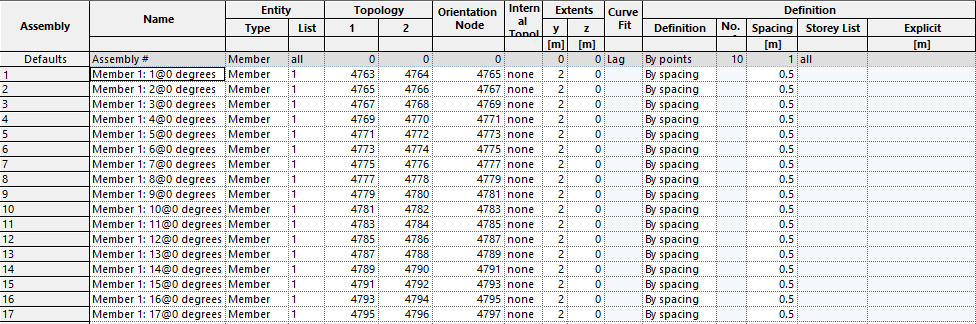
-
Enter assembly values directly into the table, or bring up the Assembly definition Wizard by double clicking on a cell, or selecting the Wizard icon in the top toolbar

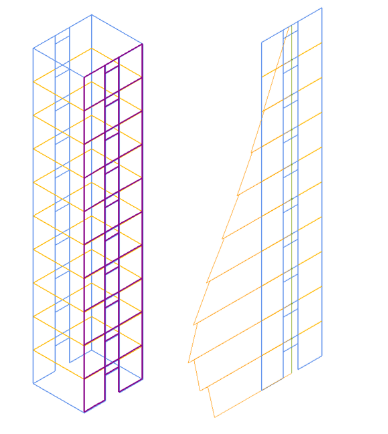
Example 1a: Wall
Entity type: Member
Entity list: Member list. In this example, 1.
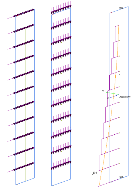
Topology: Ends 1 and 2 are along the centreline of the wall. The Orientation node is used to define the assembly xy plane. To maintain consistency with 1d element results the orientation node should be offset out of plane from the truss, so that represents major axis moments.
If the orientation wall is set within the plane of the wall then wall major axis moments will be represented by .
Extents: None defined in this example.
Definition: By storey in this example. This is suitable when no significant loads are applied between storeys.

Example 1b: Wall strip
This is based on the same member as the example above. However, Topology and Extents are adjusted to suit a 1m wide strip at the edge of the member.
Topology: Ends 1 and 2 are offset 0.5m from the end of the wall.
Extents: Limited in the assembly z axis to a 1m zone. In this example, this represents the end 1m width of the wall only. The results calculated are then taken only from this zone, rather than the entire entity.


Example 2: Truss

Entity type: Element
Entity list: Element list, e.g. '1 to 35'
Topology: Ends 1 and 2 are along the centreline of the truss. The Orientation node is used to define the assembly xy plane.
To maintain consistency with 1d element results, the orientation node should be offset out of plane from the truss, so that represents major axis vertical moments.
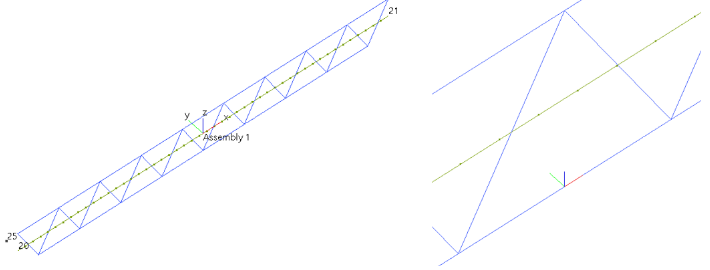
Extents: None defined in this example.
Definition: To suit the scale of the truss. In this example, the assembly is split into 50 equally spaced portions.
Note: No results are calculated between points, so if max / min results occur between points they will not be displayed.

Creating an assembly using GSA tools
There are tools in GSA to make it easier to create assemblies, found under Sculpt > Assembly operations in the top menu. From here you can choose from Create wall/core assembly or Generate assemblies for 2D members.
Note: All assembly definitions are generated automatically, but can also be edited manually.
Create wall / core assembly
This creates a single vertical assembly for a group of selected members, centred along its axis. By default, results are calculated every storey. If storeys have not been defined these will be generated automatically.
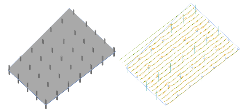
Generate assemblies for 2D members
This enables the creation of multiple regular fixed width assemblies across the full width of any individual member, at a user selected orientation.